In a photography and design studio, located in a large industrial park, a RCD tripped frequently. Due to the permanent power outtages, the employees of the studio could not work properly. This situation required a quick solution, but even electricians could not find the cause of the power outtages. To solve the problem, an in-depth network analysis is required.
To conduct the analysis, an electrical company tried to detect the fault in the photo studio, which is located on the first floor of a multi-level building. A common fault for tripping a RCD is a faulty contact point between a neutral conductor and earth or an insulation fault with a fault current conductor to earth behind the RCD.
Finding solutions
First, the electricians conducted the following steps:
- Disconnecting all consumers and carrying out an insulation test of all lines behind the RCD.
- Carrying out a VDE 0701-0702 test of all connected devices in the photo studio.
The insulation measurement with 500 V DC was carried out from the protective conductor (PE) against th neutral conductor (N) and then protective conductor against all external conductors (L1, L2, L3). In all cases, the insulation resistance of all lines was > 1 MΩ and therefore, a fault could be eliminated at this point. The insulation test of all devices also showed no insulation faults, which meant that they could be ruled out as the cause of the RCD tripping.
As the insulation test did not point out the cause of the tripping, all circuit breakers in the distribution grid of the photo studio were switched off. These breakers were activated one after another to find the feeder, which triggered the RCD. For a first quick solution, the circuit breaker containing the faulty feeder could be left switched off so that at least all other consumers in the photo studio could continue to operate without faults. By executing this plan, the electricians realized that the RCD even trips when none of the circuit breakers are switched on. At this point the electricians were at their wit’s end. What else could cause the RCD to trip?
- All consumers are disconnected from the mains via the circuit breakers.
- All cables and all consumers have passed the insulation test and can be ruled out as the source of the fault.
Further investigations beyond the energy distribution
However, there is another company located in the building, which uses frequency inverter-controlled drives for the production and machining of metal parts. In order to find the reason for the false triggering of the residual current device, the following measurement set-up was installed and the cause of the tripping was searched using high-quality measurement technology.
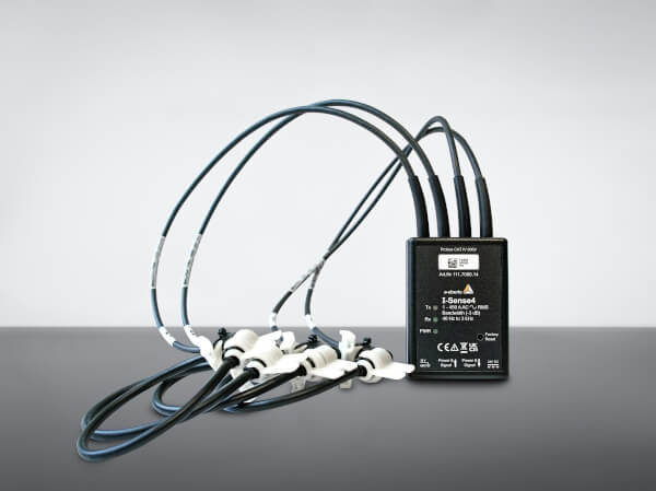
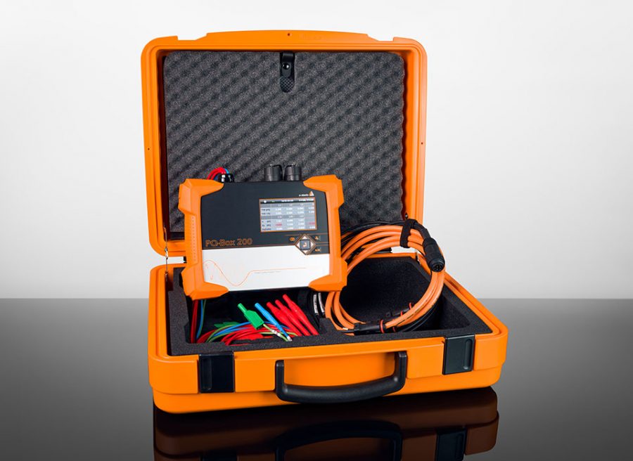
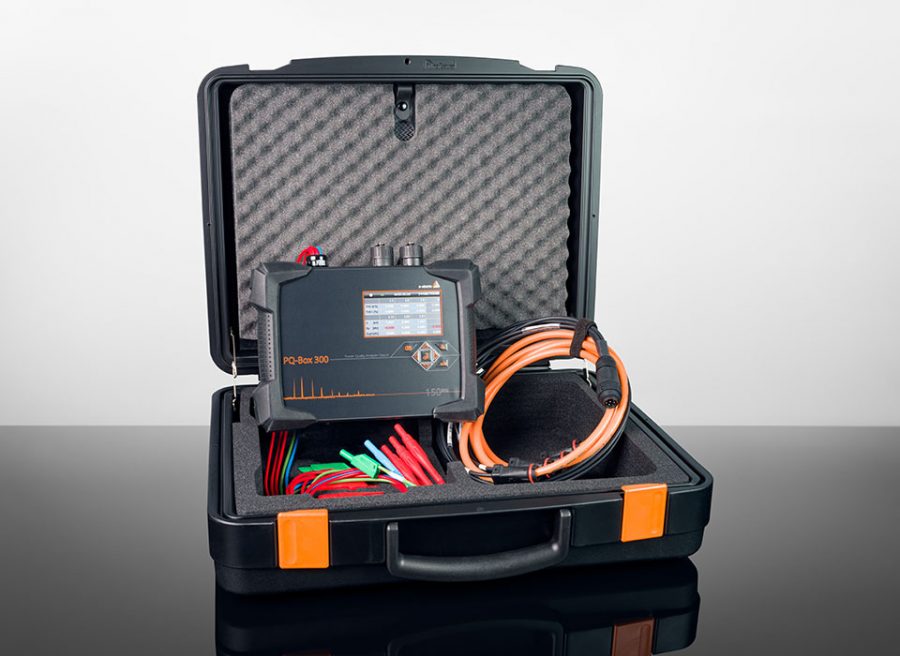
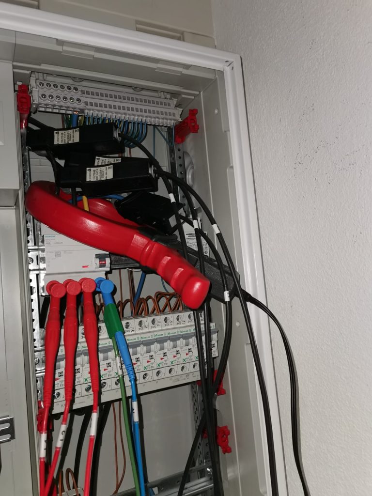
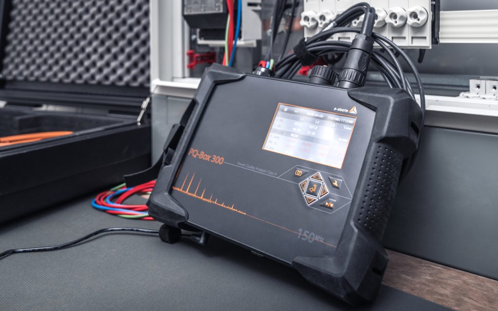
As displayed in picture 1, the network analyzer PQ-Box 300 from A. Eberle is used to measure in the sub-distribution of the photo studio. The black current clamps are used for the conductors L1, L2, L3 and N record the currents via our RCD, while a fifth current clamp (red) additionally records the differential current. The differential current is the sum of the three phase currents and the neutral conductor and thus the current that is also evaluated by the RCD and the cause for the tripping.
At any time, the sum of the instantaneous values of the currents L1, L2, L3 and N should add up to the value of 0. The resulting differential current, recorded using the the fifth current clamp, thus corresponds to the current flowing the earth as fault current or leakage current. The voltages were connected to the output of the RCD via magnetic gripper, as shown in Fig. 1. This magnetic gripper are quite convenient and quick to fit in any installation, as the screws of circuit breakers are always ferromagnetic, and thus magnetic taps can be adapted very easily and in a few seconds.
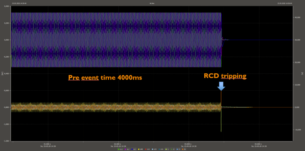
In the settings of the measuring device, the trigger threshold for fast fault records has now been set to the voltage. As soon as the mains voltage drops to 0 V by switching off the RCD, the power analyser should start a fast recording of all samples at 400 kHz.
Usually, power analysers record a large post-history as a result of an event. In this case, however, the measuring device only receives its trigger pulse at the end of the disturbance and at this point, for the evaluation it is interesting to have a history as long as possible. High-quality power analysers keep oscilloscope images in a fast RAM for a long period, even if no set limit value is exceeded. Figure 2 shows one of these events.
Analysis of the measurement data and Explanation of the problem
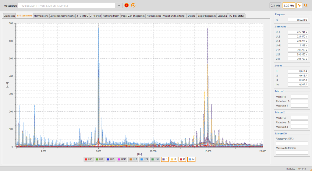
The frequency spectrum can be calculated from the sampled values shortly before the RCD is triggered using an FFT (Fast Fourier Transformation) analysis. In general, a measuring device can only calculate the spectrum up to a maximum of half the sampling rate. The PQ-Box 300 can calculate the spectrum to up to 170 kHz. The frequency analysis of the voltages and currents recorded during the fault show frequencies at 8 kHz, 16 kHz, 24 kHz and 32 kHz before the RCD tripped (Fig. 3). Using the gathered data, the search for the cause continued. These frequencies are not generated by any consumer in the photo studio and must therefore be introduced into the electrical grid from the outside. In addition, the RCD tripped even when all the circuit breakers were switched off.
Note: Most clamp ammeters as well as simple mains analysers’ usually only measure up to 2 kHz – thus the leakage currents that occurred here would not be measurable and would therefore often not be noticed.
Cause identified: Frequency converter-controlled drive
The high frequencies of 8 kHz and their multiples can only be generated locally in the low-voltage network. It cannot be assumed that these high frequencies are transmitted via a transformer. Thus, the search was limited to this building, which is equipped with its own 400 kVA transformer. On the ground floor of the same building, a production plant with some inverter-controlled drives is located. From these plants, the high frequencies are emitted into the grid via the plant current.
Since the transformer (XL) of the building has a high impedance for high frequencies (see the commonly known formula 1), these introduced interfering signals of 8 kHz and their multiples usually seek other consumers nearby with a low impedance. These are mainly devices with built-in capacitors, such as switching power supplies. Formula 2 indicates this state (the imaginary components are left out for simplification):
X_{L} = ω* L\hspace{5mm} with \: \hspace{5mm}ω =  2 *π*f\\
X_{C} = \frac{1}{ω*C}\\\
\\
X_{L} = Inductive\ reactance\ (inductance,\ transformer)\\
X_{C} = Capacitive\ reactance\ (capacitance,\ capacitor)\\
ω = Circular\ frequency\\
L = Inductance\\
f =Frequency\\
C =Capacitance\\
The formulas 1 and 2 indicate that inductances for high frequencies have a high reactance and capacitors a very low reactance. The same applies to the impedance as a complex resistance. All consumers installed in the building significantly determine a disturbance level expansion of higher-frequency disturbances (also called supra harmonics).
Explanation of the phenomenon
The inverter-controlled drives on the ground floor generated mains feedback in the frequency range of 8 kHz and multiples thereof. These levels will hardly flow in the direction of our 400 kVA transformer because it has a high impedance for high frequencies (see formula 1; Fig. 5). These clock frequencies seek out to other consumers in the vicinity, which have a low mains impedance for these frequencies. In this case, a current flows via the outer and neutral conductors towards the consumer.
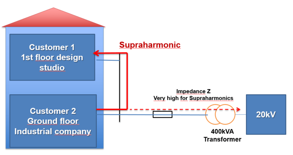
The mains filters in the various consumers of the photo studio generate leakage currents to earth. All consumers must have such EMC filters to obtain the CE mark. Since switched-mode power supplies themselves also produce conducted interference, these devices must be connected to filters. Most times, simple passive components such as current-compensated mains chokes and X/Y capacitors (Fig. 5) are used.
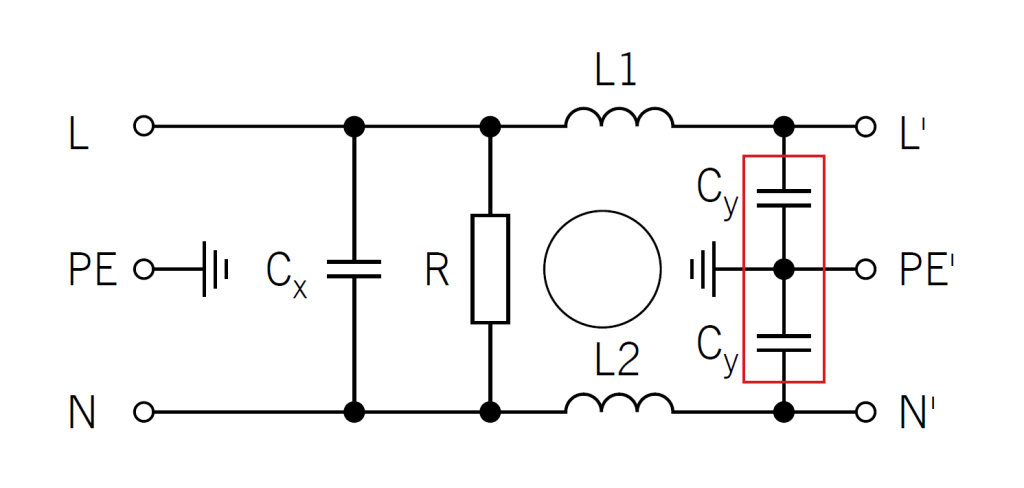
As it is not clearly defined, which position the outer conductor and the neutral conductor take when connecting a single-phase consumers via a Schuko socket, filters are found on both conductors: outer conductor to earth and neutral conductor to earth. The resulting leakage currents are predominantly capacitive, while fault currents have a high ohmic component.
An RCD cannot distinguish between a residual current and a leakage current. It must trip as soon as its current threshold is exceeded. For a 30 mA RCD, this tripping threshold is set between a minimum of 15 mA and a maximum of 30 mA. An RCD must trip between 0.5 x In to 1 x In, that is its task.
Due to the large number of consumer devices in the photo studio, such as lighting equipment, cameras, monitors, PCs and servers, the total tripping current of the RCD exceeds at 15 mA or 30 mA. To protect human beings, the tripping value is limited to 30 mA and this value should not be exceeded. This means that in our case a 300 mA type should not replace it.
The RCD now recognises a residual current due to the sum of the leakage currents of all loads. This flows via the active conductors to earth or, if all circuit breakers are switched off, between the neutral conductor and earth and thus triggers the RCD. This effect is not noticeable in an insulation measurement, as this is carried out with a DC voltage.
Problem solving
There are several solutions to this problem:
- Installation of a mains filter directly in front of the sub-distribution of the photo studio on the 1st floor
- Installation of a mains filter at the source of the mains feedback on the ground floor
- Replace the RCD with a suitable type for these mains conditions
There are many different types of RCDs for different applications nowadays, e.g. AC, A, B, B+, F. A solution for our mains feedback problem would the replacement of the RCD in the distribution grid e.g. with a Doepke type B SK. With this type of RCD, the tripping current for higher frequencies is above 30 mA for 50 Hz. High frequencies are not as dangerous for humans as 50/60 Hz currents and thus a higher tripping value may be used here (see e.g. [1]).
Since we also wanted to avoid interference from other units in the building, we additionally decided to install a mains filter in the supply line of the company causing the interference on the ground floor. This eliminates the high clock frequencies directly at the point of origin.
Conclusion
Higher leakage currents could be expected in industrial plants with power electronics. These currents can cause residual current circuit breakers to trip unnecessarily. However, the causes of tripping RCDs provoked by companies, which are not part of the local electrical distribution, are difficult to detect.
Due to the changes in energy technology, we are increasingly discovering mains feedback in the higher-frequency range of 2 kHz to 150 kHz in our energy supply grids, caused by converter-controlled drives or switching power supplies. These higher-frequency repercussions also cause new disturbances that were previously unknown. Voltage quality standards such as the IEC or DIN EN 61000-2-2 [2] already include limit values for the public low-voltage grid of up to 150 kHz. In order to detect disturbances in these frequency ranges, it is important to check before the measurement whether the used measuring device or current clamp can detect faults in this frequency range at all. Every measuring device and every current clamp has a limited frequency range that must be checked before conducting a power quality measurement.
Literature
[1]
Allstromsensitive Fehlerstromschutzeinrichtungen (RCD Typ B)
Anwendungshinweise und technische Informationen (Handbuch Allstromfibel). Doepke Schaltgeräte: Oktober 2019.
Erhältlich unter: www.doepke.de/de/produkte/schuetzen/fehlerstromschutzschalter-rccb/
[2]
DIN EN 61000-2-2 (VDE 0839-2-2):2020-05 Elektromagnetische Verträglichkeit (EMV)
Teil 2-2: Umgebungsbedingungen – Verträglichkeitspegel für niederfrequente leitungsgeführte Störgrößen und Signalübertragung in öffentlichen Niederspannungsnetzen.
Author
Jürgen Blum, Product Manager Power Quality Mobile