In this article, which we created together with the web portal Schutztechnik.com, we discuss the current changes in the energy technology. In addition, we will look on the effects of grid repercussions and what influence they have on measuring devices with which we detect faults in the grid.
Increasing energy efficiency and reducing costs – not possible without changes
Many old consumers nowadays are exchanged for power-controlled technology (cf. Figure 1). A good example is the change from an asynchronous motor to a frequency converter with a controlled drive. The asynchronous motor had two states: on and off. The frequency converter, on the other hand, can be set to the exact power required. These modern consumers bring a mains feedback to our grid: They no longer need the voltage and current to be sinusoidal, but instead build up the power and current as they would like it via a rectifier in the input.
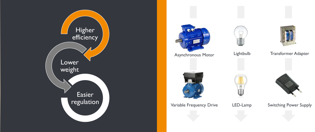
Figure 1: Changes of the electronic components
How is a rectifier constructed?
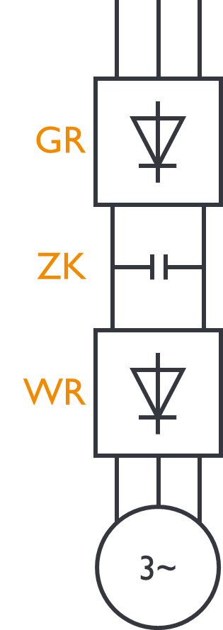
A typical input circuit of a drive can be seen in Figure 2: At the top, the mains side is shown, it is fed in three-phase and it goes via a bridge rectifier to an intermediate circuit, where this wavy DC is first smoothed out a little. Then we go to an inverter, where the DC is chopped up into small blocks and from this, we can assemble any frequency with which the motor can be regulated or controlled. This is very efficient, but on the grid side we get the switching frequencies of the inverter. Figure 1 shows a few examples of consumers that are used in today’s grids. From the figure, it can be deduced that feedback effects of 2 kHz to 300 kHz must be expected, which can be a disturbance for other loads.
If a consumer operates with a certain switching frequency, the source feeds this frequency into the grid. Now this frequency naturally seeks out some consumer and wants to short-circuit itself. At 10 kHz or 20 kHz, we can assume that it does not want to flow towards the transformer or medium voltage, because the transformer blocks high frequencies via its XL. However, when we feed in, we look for a source with a low impedance through which this frequency can flow away, and this is usually always a consumer in the vicinity.
What problems might occur in the grid if these switching frequencies occur?
Many consumers nowadays no longer have a switch. In the past, for example, a lamp could be switched on and off via a switch, but nowadays it is also possible to use a touch dimmer lamp. By touching the base, the light is switched on and off. There is a practical example of how these lamps influence the power quality:
A hotel has equipped all rooms with such touch dimmer lamps. These lamps switched themselves on and off, which is particularly unfavourable. The cause of all this: In the town where this hotel was located, an industrial company with CNC machines, which also worked during the night on weekdays, caused repercussions in the network. This ultimately caused the lamps to switch themselves on and off. In the lamp, the switching on and off mechanism is controlled by very small signals of a higher frequency. If the identical frequency is generated by another consumer or machine in the grid, a reaction or malfunction might occur.
In addition, it can be said that all feedback effects that occur in the range up to approx. 16 kHz can be perceived acoustically by humans, since consumers can convert these feedback effects into sounds.
How can disturbances be measured?
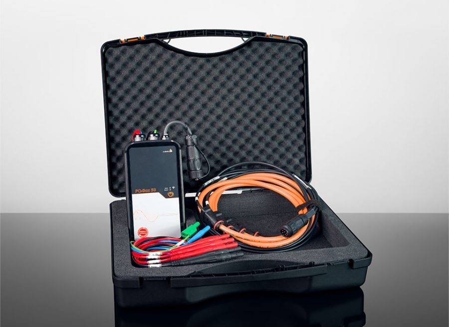
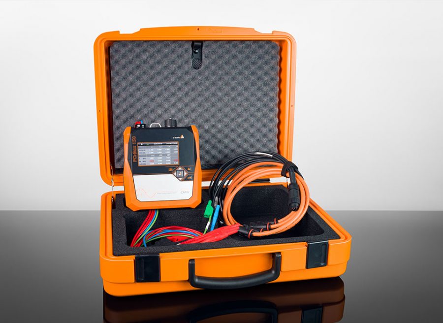
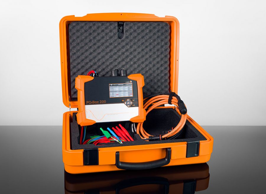
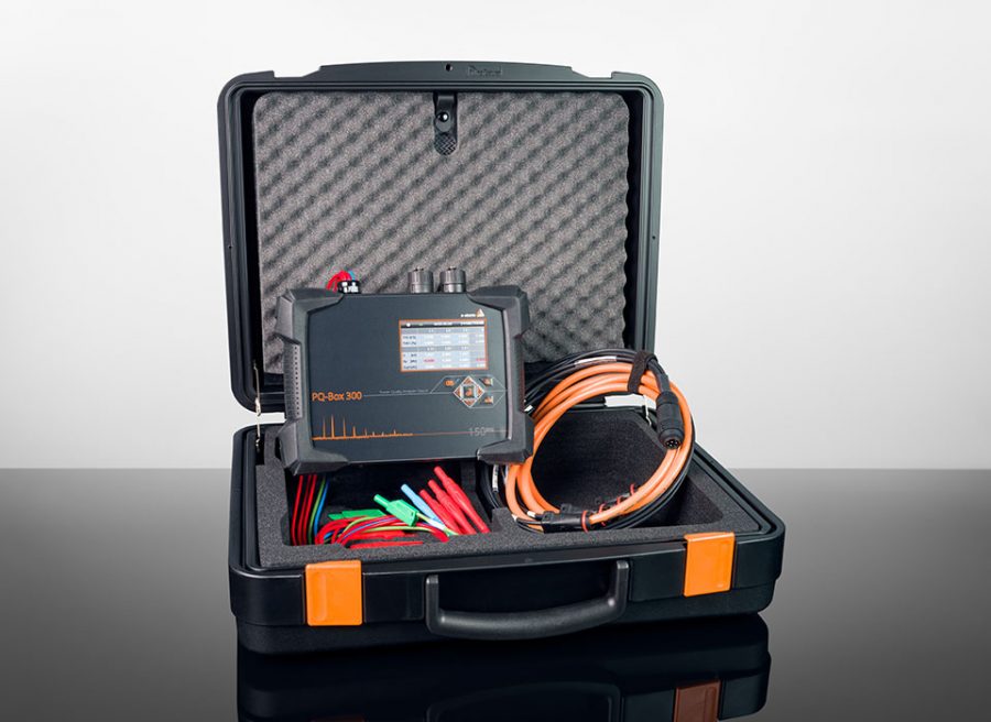
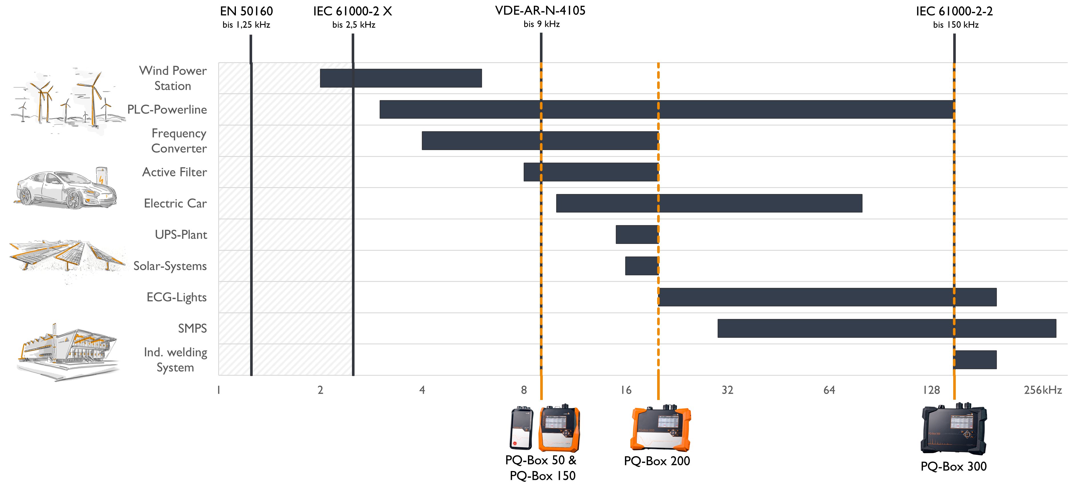
If you want to record the disturbances in the network, the whole thing is subject to the condition that the measuring device must be able to scan twice as fast as the disturbance that is to be recorded. For example, a disturbance in the range up to 10 kHz can only be detected by a measuring device that measures with at least 20 kHz. A brief overview of the sampling rates at which our mobile PQ measuring devices can measure and detect repercussions are displayed in Figure 3.
An example from practice
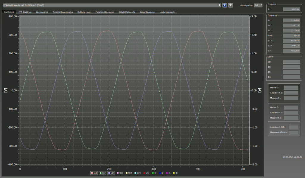
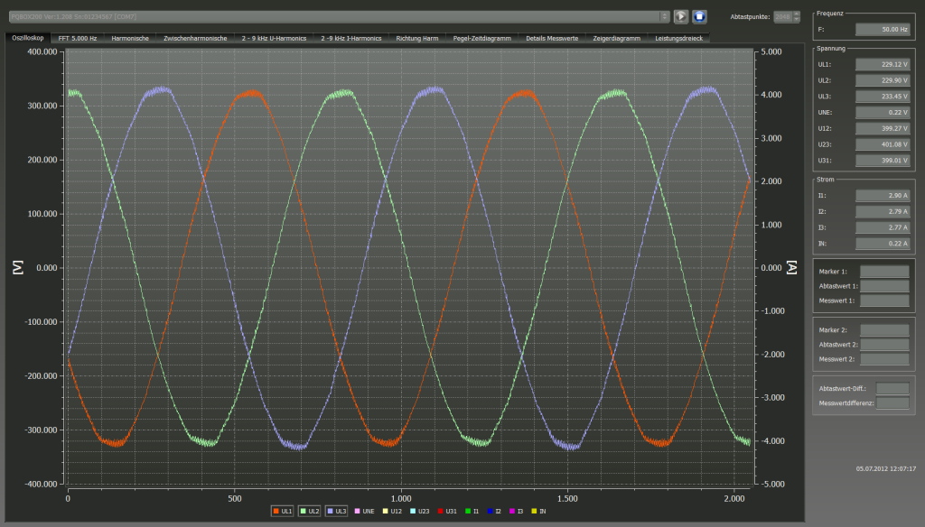
In one village, some customers complained to the energy supplier that some consumers were showing malfunctions or that devices were emitting whistling sounds. In this network, a measurement was carried out with a PQ-Box 100 (sampling rate 10 kHz) which is displayed in Figure 4. The measurement displays a perfect sine wave. There is no sign of interference at this point.
Using another device with a slightly higher sampling rate of 40 kHz (see Figure 5), we can see that a high frequency is modulated onto the sine.
The aim must now be to detect this frequency and to find the cause of this frequency by answering the following questions:
- What frequency is it?
- What is the level of this frequency?
The detection of the frequency in question is necessary because, depending on the impedance of the end user, it can lead to heating and also to malfunctions.
Author
Jürgen Blum, Product Manager Power Quality Mobile