The following technical report examines various methods for measuring current. It discusses how currents are measured using power analyzers and current clamps. The respective advantages and disadvantages of different technologies such as shunts, normal current clamps, Hall effect sensors and Rogowski coils are considered. The possible measurement errors are also addressed.
1. Current shunt
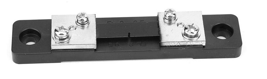
The use of a shunt is particularly suitable when high precision is required in the measurement, as is the case, for example, in engine test benches. A very accurate resistor, for example with a resistance value of 0.1 Ohm, is used. The current flow of 100 amperes through the shunt results in a voltage drop of 10 volts, which is linearly proportional to the current flowing through it. The measurement principle is very accurate and allows recording of high frequencies as well as AC and DC signals. The disadvantage is that the shunt must be installed in the mains, which is usually too costly for short-term measurements with a mobile power analyzer. It should be noted that the current shunt can be installed in the phase with high potential to ground, as well as in the N conductor. It is important to consider the potential at which shunts are located when using them. For example, a power analyzer might measure the voltage output of 10 volts but a potential of the shunt to ground could overload the meter. Therefore, it is important to carefully consider whether the use of a shunt is favorable in a particular application and whether the meter is also rated for the high potential.
2. Current clamps with metal core
The conventional technique for measuring current is to use fixed current clamps. These work on the principle of a transformer. The scheme of such a clamp is shown in the figure. The current cable is considered as winding 1. Via an alternating magnetic field in the iron core, a current is induced in the second winding, which is indirectly proportional to the current in the conductor.
For example, if a current of 1000 amperes flows in the conductor and the transformer has 1000 windings, the current at the output of the current clamp will be 1 ampere. The ratio between the two currents is therefore 1:1000.
Modern current clamps often have a terminating resistor which does not supply a current at the output, but a voltage in millivolts proportional to the current. However, the measuring principle remains the same. This makes it possible to leave the current transformer connected to the mains without danger and to disconnect it from the measuring device. This current transformer does not necessarily have to be short-circuited, unlike current-to-current transformers which must not be
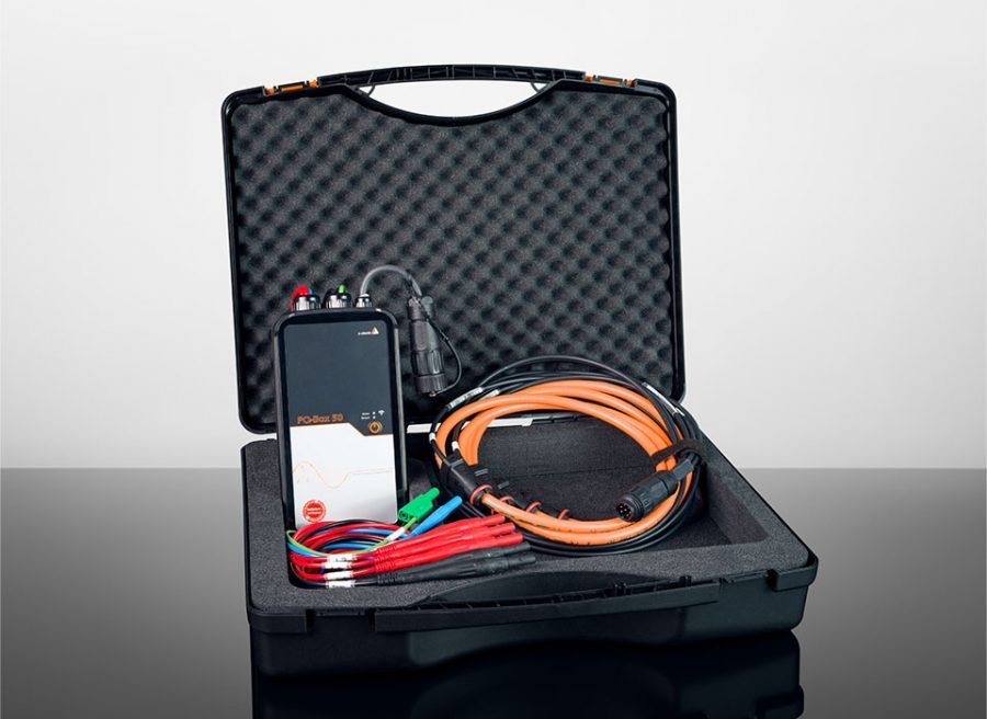
operated in the open state. Special care must be taken when using current clamps with metal cores, as even a small air gap can lead to large measurement errors. To avoid this, an interlock has been built into the mini current clamps of the PQ-Box. However, at higher currents, such as in the 1000-3000 amp range, the clamps become very heavy, large and unwieldy, making
maneuvering around large conductors difficult. In this case, the use of Rogowski current clamps is a more practical alternative.
3. Hall sensor current clamps
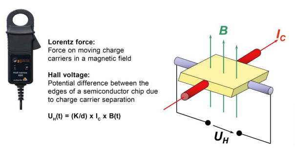
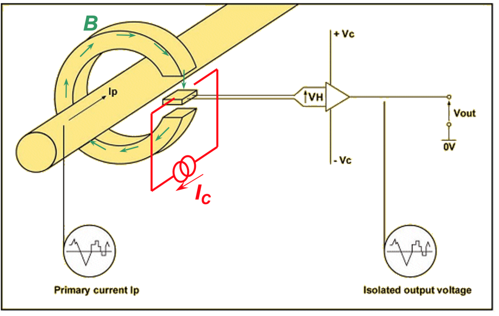
If both AC and DC signals are to be measured, the effort required for the measurement technology is somewhat greater. A passive clamp cannot be used in this case. Instead, the Hall effect can be used in metrology. This involves a semiconductor component to which a current
flow is connected. When this semiconductor element is in a magnetic field, charge carrier separation occurs in the Hall conductor component. This implies that the charge carriers are shifted to one side in the magnetic field. This voltage of the Hall sensor element is proportional to
the magnetic field. With this effect, both AC and DC currents can be measured.
The use of AC and DC current clamps has both advantages and disadvantages. Although these clamps are used very frequently, they are not used as standard in all measuring devices. One disadvantage of these clamps is that they are sometimes very sensitive to temperature.
Usually, one has to calibrate a DC current clamp to the value 0 via a key or a rotary knob before each measurement. However, this can lead to relatively large errors in the measurement technique for long measurement periods, such as monitoring a solar system over 7 days, due to temperature fluctuations between day and night.
Another limitation is the need for a power supply. Most current clamps are designed to run on batteries, which is inconvenient for longer measurement periods. However, there are clamps that can be powered by an external power supply, allowing for longer measurement periods. When using current clamps, it should always be noted that there are various sources of measurement error, such as temperature drift.
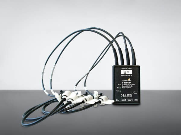
4. Rogovski coils
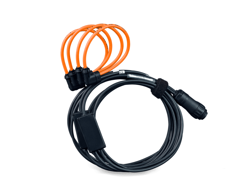
Rogowski clamps are very user-friendly, as they are available in all lengths and sizes, and are very flexible in design. One customer request is for the clamp to be as thin and small as possible, so that these loops can be accommodated even in very confined spaces. However, the advantage of a very thin current loop also comes with a disadvantage in terms of measurement technology.
The output signal depends on the diameter of the head. A larger diameter leads to a larger output signal. Therefore, although a thin clamp can be used in tighter spaces, the output signal is lower and thus smaller currents can only be detected with a larger measurement error. This is a
limitation of physics that cannot be circumvented.
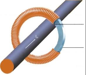
A Rogowski coil consists of a rubber core that behaves magnetically like air and is therefore also called an air coil.
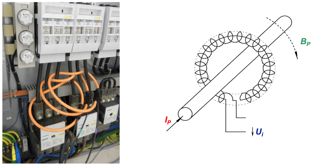
To reduce measurement errors when measuring small currents, it is possible to wind the coil twice around a conductor. Since the measured value would now be doubled, this can be corrected very easily by adjusting the transformer ratio in the settings of the PQ box to the factor x0.5.
It should be noted that Rogowski current transformers can only measure AC currents and not DC.
Each Rogowski coil needs an integrator at the output to trace the output signal back to the original current signal. Most Rogowski coils have electronics built into the cable, which usually also requires a power supply. All PQ boxes from A-eberle have two separate current inputs. One input for current clamps and one input for Rogowski coils. Due to a coding in the plug of the current clamp, the measuring device automatically recognizes the correct clamp type. A power supply for these current clamps is therewith not necessary, additionally the precision is improved, as the measuring signal is not converted twice.
With regard to measurement errors, the information on the current clamp supplier’s data sheet should be taken into account
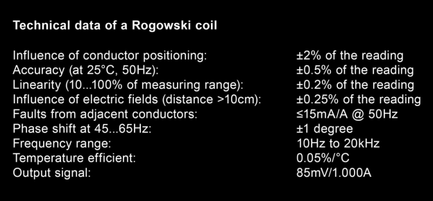
Calibration and manufacture of the clamps provide relatively small measurement errors of 0.5 percent of the measured value when using Rogowski current clamps. The greatest error factor is often the position sensitivity of the clamp. Optimum accuracy is achieved when the conductor is positioned exactly centered in the middle of the clamp. In practice, however, the positioning of the conductor influences the measurement result by up to 2%. Other factors that influence accuracy are linearity, temperature influences and neighboring fields. Thus, currents in
neighboring conductors also influence the measurement result. This error is up to 1 % of the neighboring currents. It becomes problematic when measuring small currents in the vicinity of conductors with large currents. There, the error can also be up to 100 percent of the measured
value. It is therefore necessary to carefully consider the ambient conditions, especially when measuring low currents.
The use of mini current clamps is usually more suitable for the measurement of very small currents.
Angular errors
Measurement errors, especially angular errors, can be caused by the sampling of voltages and currents. As a rule, voltages are tapped off in a fixed manner, while currents are measured with the aid of current clamps. However, each current clamp has a slight phase error, which can cause the measured current to be displayed leading or lagging. The meter calculates all the powers from the samples of the voltages and the currents.
As an example, it will be shown how angular errors are noticeable in the power measurement quantities.
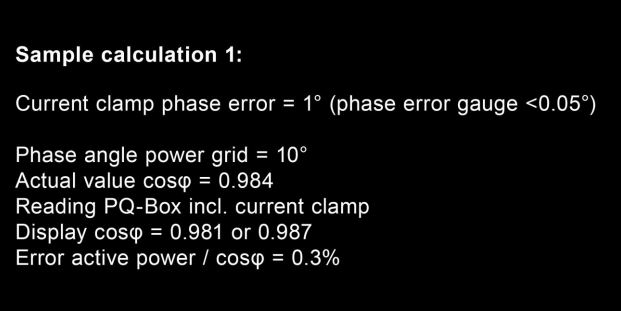
An example 1 is a network where the cosphi is quite good, with a phase angle of 10 degrees between fundamental voltage and fundamental current. A phase error of a current clamp of one degree can give the following measurement results in the meter display for an actual value of 0.984 for the cosphi: Max: 0.981 or Min: 0.967.
This corresponds to an error of 0.3 % for the cosphi as well as for the active power.
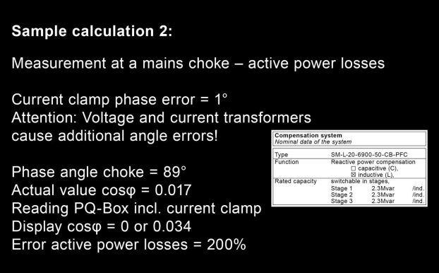
In example 2, a measurement at an extremely large phase angle is used. This application is to determine the active power losses at a line reactor of 2.3 MVA reactive power in a medium voltage network. The cosine Phi of this inductor should be 90 degrees if possible. In our case, the
phase error is 89 degrees.
An additional angular error of one degree of the current clamp or even of a secondary measuring transformer can now lead to a measuring error of up to 200 percent.
In this case, the active power losses of this coil can now be between 0 and 200% of the true measured value. However, for the reactive power in this case the measurement is very precise.
For evaluations in the network where correct angle measurements are very important, such as when measuring in a medium voltage network or via current transformers in a low voltage network, the correction of the angle errors of the various transformers can become very important.
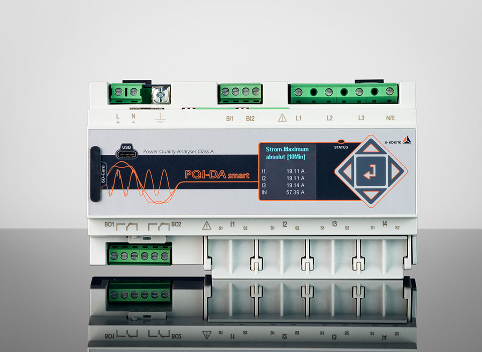
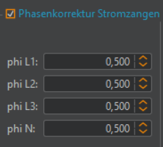
In all PQ boxes, an angle correction factor can be stored for the calculations of the power measurement quantities and phase angles. This allows angular errors to be corrected very easily for measurements where the angular error is crucial.
Author
Jürgen Blum, Product Manager Power Quality Mobil