This topic is divided into two posts (Tips and Tricks Part 1 and Part 2). This is the part 2.
Theoretical basics
When using mobile network analyzers, the question often arises as to how the measuring device can be supplied with power, since power outlets are rarely available in the vicinity. This applies both to the house connection and to cable distribution boxes outdoors or, as shown in the example below, at a concrete pole station.
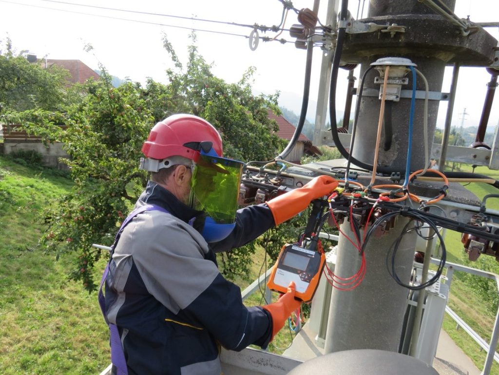
One possibility is to connect the measuring device directly via the voltage taps at the measuring point. However, it is important to ensure that the voltage to which the device is connected corresponds to the technical data of the power supply unit, as the measuring range of the devices is usually greater than what the power supply unit can handle. The power supply units of the PQ boxes can be operated between 100 and 500 volts with AC or DC, however, when used in a 690V industrial network, for example, it should be ensured that the voltage is not too high, otherwise the device or the power supply unit can be damaged. Also, a voltage that is too low can harm switching power supplies as well, as it will thermally overload them due to the high current. It is important to consider the correct voltage for the power supply when connecting devices to the measurement voltages. When making measurements on voltage transformers in a medium voltage network, measurement devices could theoretically be supplied with 100V from the chained voltage, but this is not recommended.
It should be noted that switching power supplies, cause harmonics. These current harmonics cause corresponding voltage harmonics at the high load of the voltage transformer and thus falsify the result of an evaluation of the voltage quality. For a pure power measurement, the supply of the devices via medium voltage transformers can be considered.
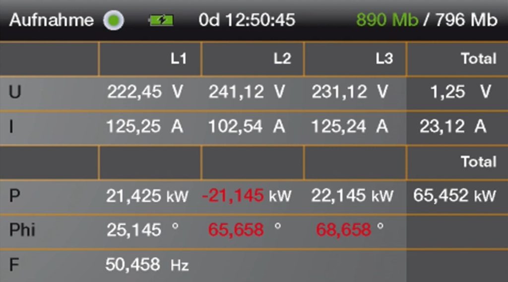
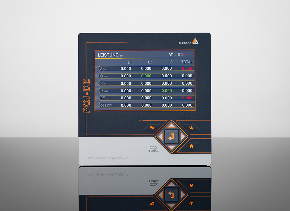
Before starting the recording for the week, it is important to check if all voltages and currents are connected correctly. This can be checked very easily via the display of the devices. When using current clamps, make sure that they are always tightly closed, as even a small opening can lead to large measurement errors.
A negative sign of the active power indicates that the system is feeding power back into the grid, while a positive sign means that the system is drawing power from the grid. If the power flow or the sign of the power is incorrect, the current clamp has been installed in the wrong direction and must be rotated by 180°.
If the assignment of voltages and currents does not match the correct phase in the network, this can be recognized quite easily in the online pointer diagram or also in the displayed phase angle between voltage and current.
Current measurement at bundle conductors
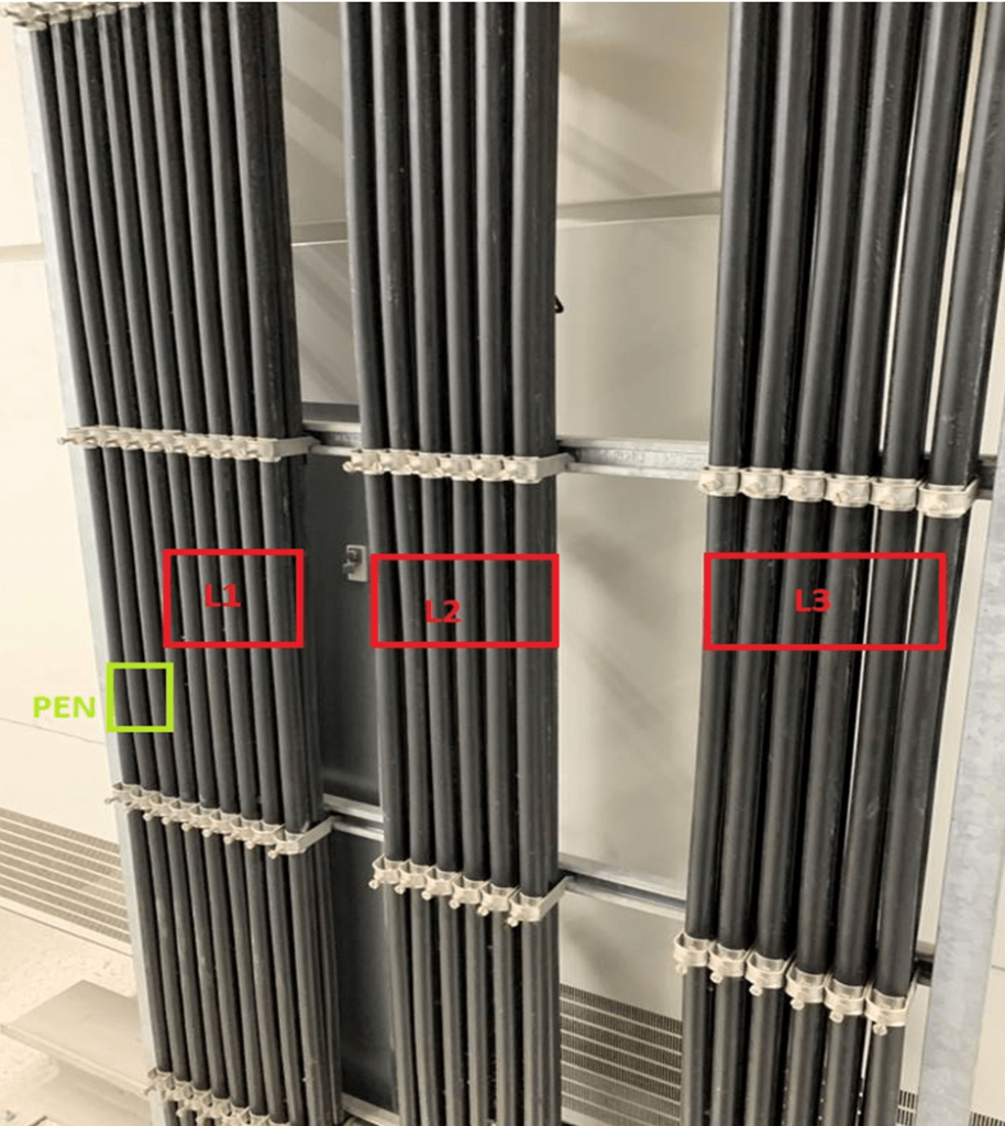
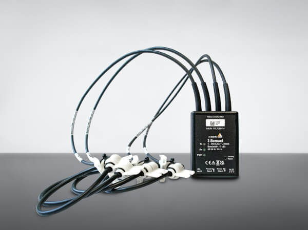
When measuring currents on bundle conductors (in this case 12 single conductors per phase), it should be noted that the currents in the individual single conductor cables can be distributed very asymmetrically. Thus, it is often not possible to place the Rogowski current clamp around only 1/3 of the cable and then multiply this measured value by 3. An alternative would be to use Rogowski coils of sufficient length and place them around the complete cable bundle.
Is my measurement device capable of detecting the desired high-frequency disturbance? An FFT analysis was performed to detect the frequencies, harmonics and switching frequencies in the local network. This local network is the subject of numerous complaints from customers. Equipment failures, malfunctions, and whistling noises in equipment or bell transformers are the most common complaints. In this example, it is the suparharmonic frequencies that clearly stand out.

The EN50160 offers only limited help with regard to the identified disturbances in the range of super harmonics. This standard is limited to the evaluation up to the 25th harmonic. There are no compatibility levels above 1,250 hertz. In comparison, the EMC standard IEC61000-2-2 has limits and compatibility levels for the public low-voltage network up to 150 kilohertz.
The measuring device and also the current clamps that are used must be able to detect the desired disturbance. As an example, the PQ-Box 100 is considered in Figure 6. This scans at a sampling rate of 10.24 kilohertz and therefore would not be able to detect the 10 kilohertz repercussion. Its bandwidth is limited to 5 kilohertz. To capture this disturbance, the PQ boxes 150 to 300 would be better suited, operating at sampling rates from 20 to over 400 kilohertz. Picture No. 6 was taken with a PQ-Box 200 and shows the interference signal in the oscilloscope image.
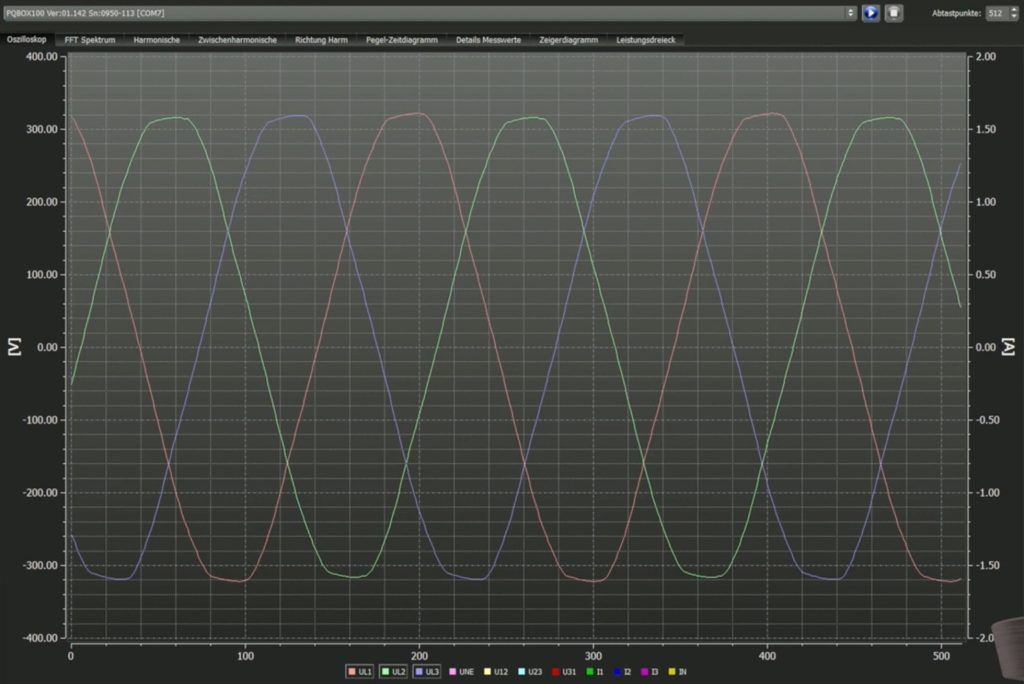
An oscilloscope image recorded with a PQ-Box 100 serves as an example here. It shows a perfect sine wave.
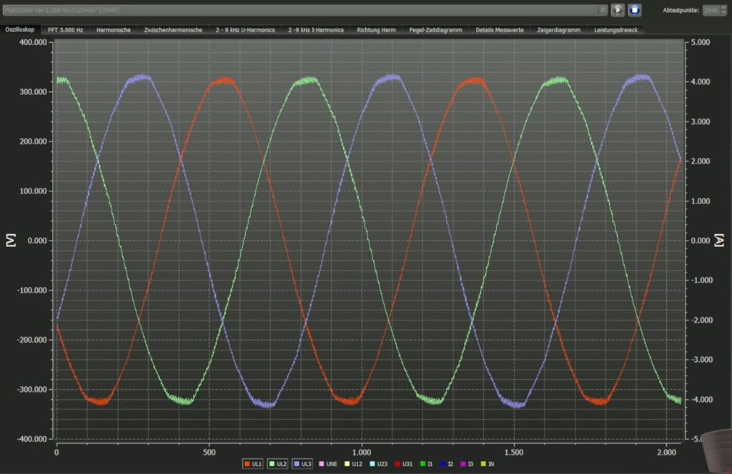
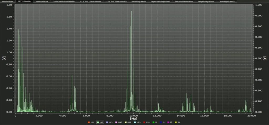
In comparison, measurements were taken again at the same measuring point using a PQ-Box 200 with a sampling rate of 40 kilohertz (Figure 7). Here, the 10 kilohertz can clearly be seen as a feedback effect with a level of 1.7 volts, which is the cause of the problems with various loads.
Trigger settings
When considering which measurement data to acquire with a power quality analyzer, it is important to choose the trigger criterion carefully. Usually, a trigger threshold is taken for when fast fault records are triggered, such as falling below or exceeding a voltage or current threshold. This setting makes it possible to record mains dips or starting currents of machines as oscilloscope image or ½ period recorder.
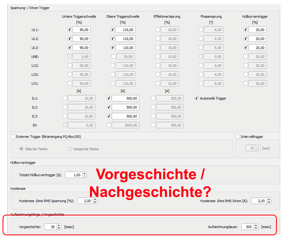
However, in order to record the cause of failures of systems or consumers, it can be useful to trigger an undershooting of a current threshold. Since the trigger criterion is usually only fulfilled when the system fails, a long history is required for later evaluation.
All PQ boxes have the possibility to record up to 600 seconds of prehistory. In this way, the evaluation of the measurement data over a long period of time before the failure of the system recognizes the reason
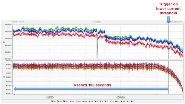
In the example, a network analysis was performed on a CHP unit that failed several times a week. A clear trigger criterion that occurs when the CHP unit fails is that a current threshold is undershot. The nominal current of the plant was 70A. A value of 60A was set as the trigger threshold. If the plant current drops below this value, the PQ box in this example records 100 seconds of pre-disturbance history and 20 seconds of post-disturbance history. The reason for the disturbance could be found via the prehistory.
Author
Jürgen Blum, Product Manager Power Quality Mobil