Use of the harmonic voltage for earth fault detection
For the study of the behaviour of the harmonic currents and voltages in the compensated network, at a first approximation the compensated network can be considered as an isolated network.
Justification
The reactance of the Petersen coil XP = ωLP increases proportionally with the harmonic frequency considered, for example, the reactance of the Petersen coil for the 5th harmonic (250 Hz) is five times as high as for the fundamental (50 Hz). On the other hand, the reactance
X_{CE} = \frac{1}{ωC_{xE}}of the conductor with respect to earth is inversely proportional to the frequency of the harmonics, i.e. the reactance of the 5th harmonic is only 1/5 of the reactance of the fundamental. This means that the capacitive current to earth with the same voltage amplitude of the harmonic at the input increases proportionally to the frequency of the harmonic frequency i.e. the current of the 5th harmonic is five times as large as the current of the fundamental.
Evaluation of the reactive power direction of the harmonic
In the first procedure for detecting the faulty output, only one direction decision is used, i.e. a distinction is made only between a capacitive and an inductive current flow. The requirement for the angular accuracy of the current transformer is thus much lower. An amplitude error in the transformer will only affect the trigger threshold.
The figure below illustrates the tripping characteristics of the harmonic procedure (a) of the tripping characteristic of the watt-metric procedure (b) compared.
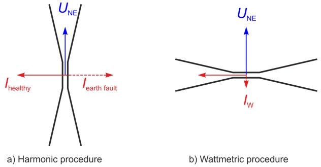
In the watt-metric procedure, the active current of the projection of the zero current is detected on the zero sequence voltage UNE. For large capacitive outputs the angular error between the current and the voltage measurement lead to large “apparent active currents”. This “apparent active currents” add to the actual active current in the respective output and can increase or reduce it. This can result in either an over- or an under- excitation of the relay.
In contrast, the evaluation of the harmonic currents is much less critical and can be reduced to a simple directional decision of the harmonic currents.
Comparative evaluation
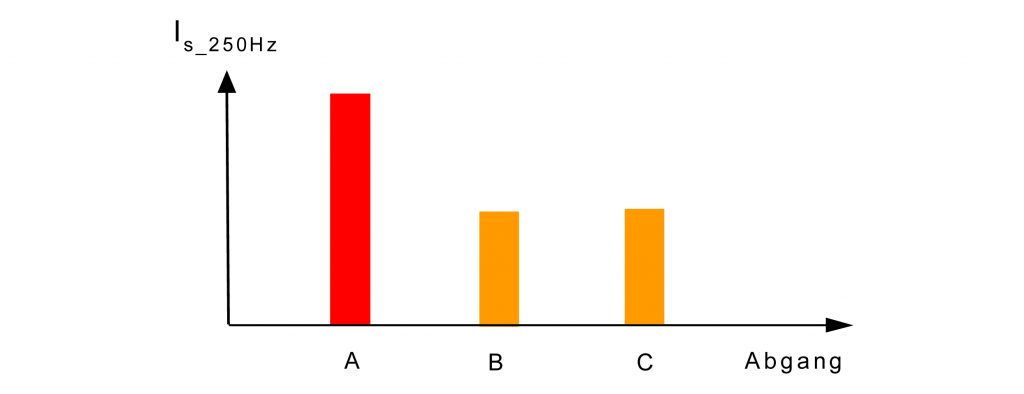
In the second procedure, the amplitude of the harmonic current is evaluated. It is important that a comparison of the harmonic currents of the individual outputs is carried out and that the output is sought with the largest relative harmonic content. This output is recognised as being faulty.
In contrast, the evaluation of the harmonic currents is much less critical and can be reduced to a simple directional decision of the harmonic currents.
Conversely, if only the magnitude of the harmonic current is to be evaluated, this would lead to daily under or over functioning of the relay. As was shown in the newsletter 14 (part 1) the harmonic voltage is highly dependent on the harmonic current in the load. The major causes of harmonic currents are rectifier circuits as used in frequency inverters for electrical drives or in TVs, PCs, and so on. Also included of course are the non-linear magnetization currents of transformers, which flow even when the transformers are idling. From the structure of the consumer, it can be concluded that the harmonic content is subject to both a day and a week course. Frequency converters are mainly used during the daytime for drives, while televisions are switched on in the evening more. The lowest values for the harmonic voltage can therefore be expected at the weekend, and in the second half of the night. But also on the basis of the mentioned magnetization currents, the harmonic currents never go to zero.
Due to this time dependence of the harmonic voltages, an absolute threshold for the harmonic current for the detection of a faulty output cannot be successful. A comparative analysis of the harmonic currents of the individual outputs, however, eliminates the temporal dependence since only the relatively largest harmonic current will be shown.
An advantage of this procedure is, however, that the direction of the connected current transformer does not have to be observed. However, at least three outputs are required where in this case the shortest output should be at least 5% of the total network to make a clear distinction possible.
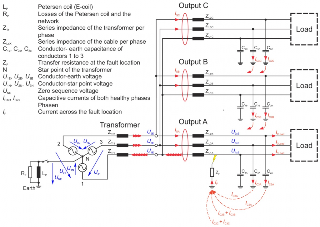
For both evaluation processes, it is important that aa large a healthy network as possible (output B and C in Figure 4) is available. From Figure 4, it is evident that the current is actually measured, which flows through the phase-earth capacitance of the healthy output. The capacitive current of the faulty output contributes nothing to the evaluation.