Regulation on the voltage
For the regulation of the voltage ULoad at a predetermined value at the specified load point (e.g. the end of a branch conductor), the load-dependent difference between the voltage at the step transformer and the voltage at the load point can be compensated by a corresponding automatic adjustment of the setpoint of the voltage regulator in order to keep the voltage at the load point constant regardless of load fluctuations.
U_{sett2} = U_{sett1} + U_{comp}Ukomp : Difference between the effective values of UT and ULoad
Voltage drop on a three-phase conductor
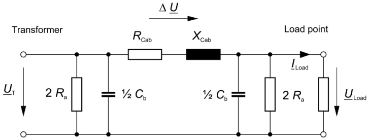
For high-voltage power lines, in the energy technology for determining the voltage difference between the beginning and end of a line, instead of the general line equations simple approximate formulas are used, where the equivalent circuit on which it is based is shown in Figure 1. The results meet the accuracy requirements of the voltage regulation, which can only be carried out in stages.
The simplification of the general conduction equation is possible with power lines because their lengths always “short compared to the wavelength l” of the fundamental of the operating voltage (l approximately 6,000 km at 50 Hz). As limits for the following approximate formulas, line lengths of about 150 km for overhead lines and 50 km for cables apply.
For the load-dependent voltage difference (phase-neutral voltage) on the three-phase line between the tapped transformer and the load point the following applies:
\Delta{U}=U_{T}- U_{Load} = Z_{Cab}*I_{Load}= \Delta{U}e^{j(φZ_{Cab}+φI_{Load})}ILoad of the current consumed in the consumer circuit at the load point
φCab angle of the conductor impedance ZCab
ILoad angle of the current ILoad at the load point
(φILoad = φULoad – φZLoad)
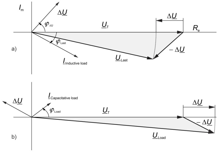
a) With an inductive load the voltage drop in the line is positive and thus the voltage ULoad at the load point is less than the voltage UT at the transformer.
b) With a capacitive load the reverse applies, i.e. the voltage at the load point is higher than at the transformer. Such loads mainly occur at night.
Line simulation
Because the actual value of the voltage on the load on the voltage regulator normally is not available, the voltage drop on the line is approximated in a line simulation of RCab and XCab, through which the current I = ILoad (w2 / w1) flows. The discharge resistance and the operating capacitance of the equivalent circuit is not taken into account and the small difference between the angles at the beginning and end of the line (transformer and load point) is also neglected.
Load-dependent voltage drop
In the series control, for the change in the set point, only the difference of the effective values of transformer voltage and load voltage is a determinant, so that the angles of the two voltages are meaningless in this context. The complex voltage difference ∆U determined from the line simulation (the impedance of the line) is not different from the difference of the two effective values, so that the complex voltage difference cannot be used directly to change the setpoint.