Earth Fault in compensated networks
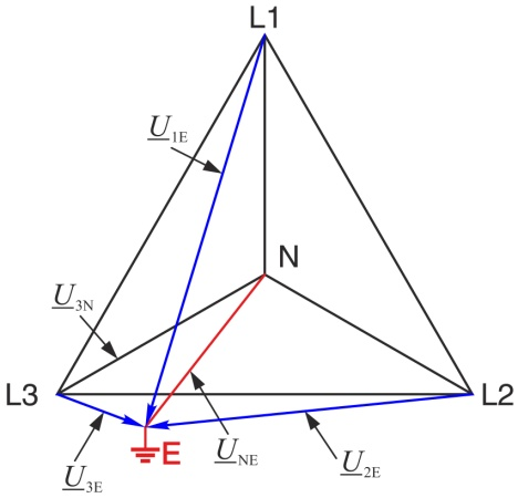
The earth fault in compensated networks is usually presented without a contact resistance at the fault location (RF= 0). In the vector diagram in the case of an earth fault the earth point then changes into a vertex of the voltage triangle.
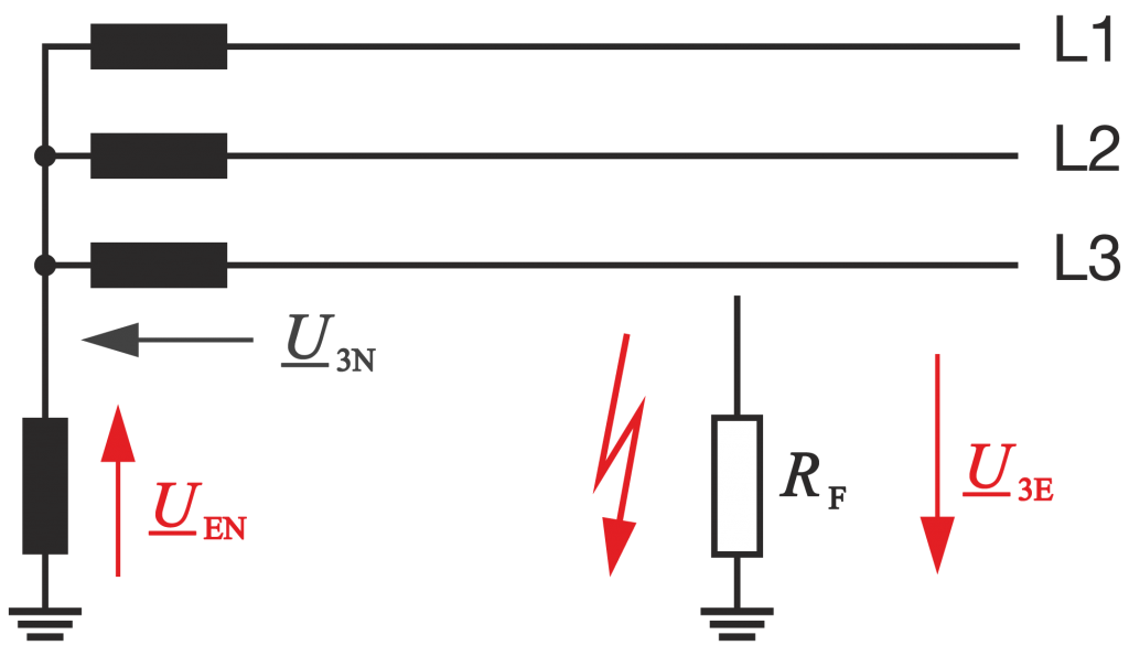
However, usually an arc occurs at the fault location with a finite resistance (RF¹0). As a function of the detuning v, the damping d and the resistance RF at the fault location, the earth point E at the fault location changes into a circular arc, in overcompensation counterclockwise and with undercompensation clockwise towards the centre of the voltage triangle. The location of the centre of the circle is determined by the detuning and damping.
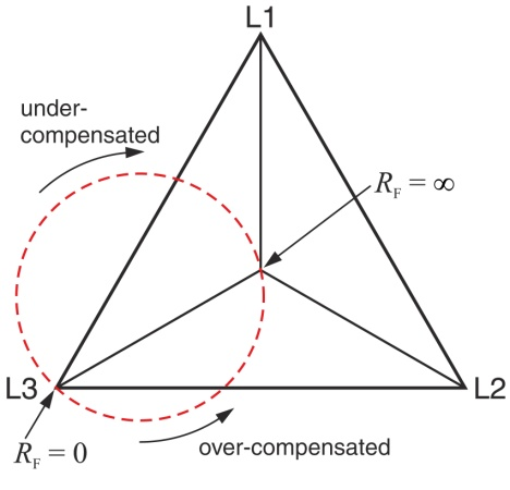
The vector diagram of the voltages then changes and thus also the voltages at the phase-earth capacitances and the earth fault coils according to the magnitude and phase angle.
The new voltages can be calculated with the aid of the symmetrical components. The zero sequence is represented by a parallel resonant circuit consisting of the phase-earth capacitance, earth fault coil and discharge resistors.
