Table of contents
What is reactive power/reactive power compensation?
Official definition: According to VDE standard 0100-710, reactive power refers to the electrical power that flows back and forth between the phase conductors and the neutral conductor of a three-phase network but is not capable of performing mechanical work. It is measured in volt-ampere-reactive (VAR).
Power factor correction is the process of balancing the reactive power present in the grid to increase the efficiency and stability of the grid. This is often done with the help of capacitors that generate opposing reactive power and thus reduce the total reactive power in the grid. This compensation is important to improve the power factor of the grid, resulting in less reactive power circulating in the grid. The power triangle is a concept that illustrates the relationship between active power, apparent power and reactive power.
Example: Let’s assume an industrial company operates several large electric motors that generate considerable inductive reactive power. Without compensation, the energy supplier would have to provide this additional reactive power, which would lead to increased grid losses and lower efficiency. By using capacitors for compensation, the company can generate its own reactive power and thus reduce the load on the grid.
Reactive power compensation offers a variety of benefits, including improving energy efficiency, reducing energy costs and increasing grid stability. In many countries, certain regulations on reactive power compensation are mandatory to ensure the quality and stability of the electricity grid.
Overall, reactive power and its compensation plays a crucial role in modern energy supply and is of great importance for companies and energy supply companies to avoid reactive power and make the grid efficient.
What is the difference to active power/apparent power?
The terms active power, apparent power and reactive power are fundamental concepts in electrical engineering that describe the relationship between different types of electrical power.
Active power (P):
Active power is measured in watts (W).
It represents the actual electrical power used by a device or system in a power grid to do work. In other words, it is the useful power that drives a motor, generates light or operates electrical appliances, for example.
Apparent power (S):
Apparent power is measured in volt-amperes (VA).
It is the total electrical power present in a power grid, regardless of whether it is actually used to perform tasks. Apparent power is made up of active power and reactive power and can be regarded as “apparent power”.
Reactive power (Q):
Reactive power is also measured in volt-ampere-reactive (VAR).
It represents the electrical power that flows back and forth between the phase conductors and the neutral conductor of a three-phase network, but does not perform any mechanical work. It is primarily generated by inductive and capacitive loads and is required for the operation of these loads, but does not contribute to the performance of tasks.
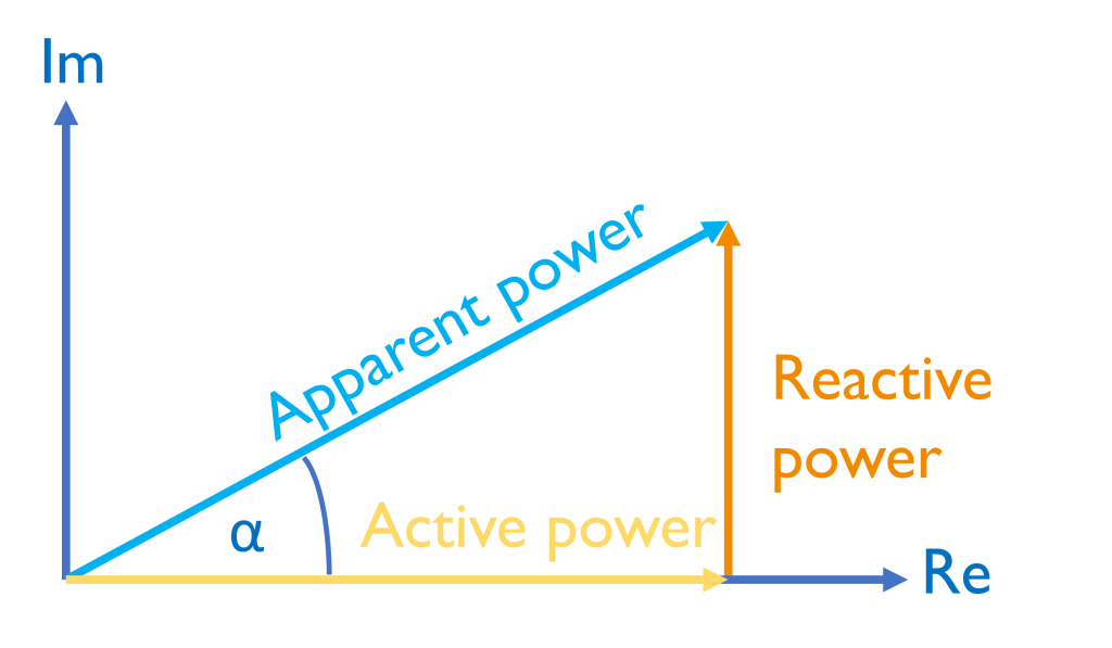
In a power triangle, which visually represents the relationships between active power, apparent power and reactive power, the active power corresponds to the horizontal side of the triangle, the apparent power is the hypotenuse of the triangle, and the reactive power is the vertical side of the triangle.
An active power meter is an instrument that measures the actual active power in an electrical circuit. It helps to monitor and control energy consumption.
To summarize: Active power is the actual, usable power, apparent power is the total power in the grid, and reactive power is the power that is not used to perform tasks but is necessary for the operation of inductive and capacitive loads. These concepts are important to understand and optimize the efficiency and stability of power grids. An active power meter is a useful tool for monitoring energy consumption.
You can gain a deeper insight into the calculation and interaction of active, apparent and reactive power in our Info-Brief 25 “Definition of power measurement parameters according to the DIN 40110-2 and IEEE 1459 standards”:
INFO-LETTER No. 22
Definition of measured power values according to the DIN 40110-2 and IEEE 1459 standards
How is the reactive power calculated?

The reactive power is calculated using the following formula:
Reactive power (Q) = apparent power (S) × sin(φ)
Q: Reactive power in volt-amperes-reactive (VAR).
S: Apparent power in volt-amperes (VA).
φ: Phase shift angle between active power (P) and apparent power (S).
The phase shift angle (φ) is crucial for calculating the amount of reactive power. It can be positive or negative, depending on whether inductive or capacitive loads are involved.
For inductive loads (e.g. electric motors), the phase shift angle is positive, as the reactive power lags behind the active power. In this case, the formula is
Q = S × sin(φ)
For capacitive loads (e.g. capacitors), the phase shift angle is negative, as the reactive power leads the active power. In this case, the formula is
Q = -S × sin(φ)
Power factor correction attempts to minimize the phase shift angle (φ) in order to reduce the reactive power. This can be achieved through the targeted use of capacitors or other compensation devices.
In addition to the formula for calculating reactive power, there are reactive power compensation calculators that can be used in more complex systems and networks to determine the exact amount of compensation required.
The unit of reactive power is Volt-Ampere-Reactive (VAR), which indicates the amount of electrical power required in a system for the formation of electromagnetic fields in inductive devices or to compensate for capacitive loads. This is an important aspect in electrical engineering to ensure the efficiency and stability of power grids.
How is reactive power measured?
The measurement of reactive power in multi-conductor circuits is defined in the standards DIN 40110-2 (Germany) and IEEE 1459 (International). The calculation methods of these standards therefore form the basis for power calculations for modern measuring devices. All devices in the A. Eberle product range – from permanently installed devices to mobile network analyzers – use the DIN 40110-2 calculation method.
Measuring reactive power is an important step in evaluating the condition and efficiency of an electrical system. Various methods and instruments are available for measuring reactive power. Here are some important aspects of measuring reactive power:
Wattmeter
A wattmeter is an electrical measuring device used to determine the active power (in watts) in an electrical system. Active power can be measured by inserting a wattmeter into the circuit. To calculate the reactive power, the formula for calculating the reactive power (Q) can be used:
Reactive power (Q) = √(S^2 – P^2), with:
- Q: Reactive power in volt-amperes-reactive (VAR).
- S: Apparent power in volt-amperes (VA).
- P: Active power in watts (W).
Oscilloscope
When measuring reactive power with an oscilloscope, voltage and current waveforms are analyzed. The phase shift between voltage and current can be read on the oscilloscope. A phase shift angle that is not zero indicates the presence of reactive power. The amount of reactive power can be calculated using trigonometry.
Three-phase current measurement
In three-phase systems, special three-phase wattmeters or three-phase power meters are used to measure active power and apparent power in the three phases. The measurement of reactive power in three-phase systems usually requires more complex instruments and calculations, as the phase shift between the phases must be taken into account.
Circuit methods
In some cases, special circuits are used to measure the reactive power. For example, the reactive power measurement can be performed with compensation capacitors to determine the amount of reactive power compensation. Here, capacitors are added or removed to minimize the phase shift angle and thus compensate for the reactive power.
It is important to select the correct measurement instruments and procedures depending on the specific requirements of the system. Measuring reactive power is critical to ensure that electrical systems are operating efficiently and stably and to determine the need for power factor correction.
Measuring reactive power with power quality analyzers from A. Eberle
With our power quality device family, consisting of mobile network analyzers and permanently installed power quality measuring devices, you have the unique option of subdividing and outputting reactive power in various independent measured variables:
- Fundamental oscillation displacement reactive power
- Harmonic distortion reactive power
- Distortion reactive power
- Modulation reactive power
- Unbalance reactive power

Significant cost reductions can be achieved, particularly when evaluating the use of filter technologies, such as harmonic filters to reduce distortion reactive power. This can also have a positive effect on grid charges. At interconnection points between the industrial grid and the public grid supply, we therefore recommend the use of a permanently installed power quality/grid analysis solution such as our permanently installed power quality analyzer with fault recorder function “PQI-DE”. The measuring device can store the various types of reactive power both locally on site and transmit them remotely to various interfaces (see illustration).
Performance measurement in practice
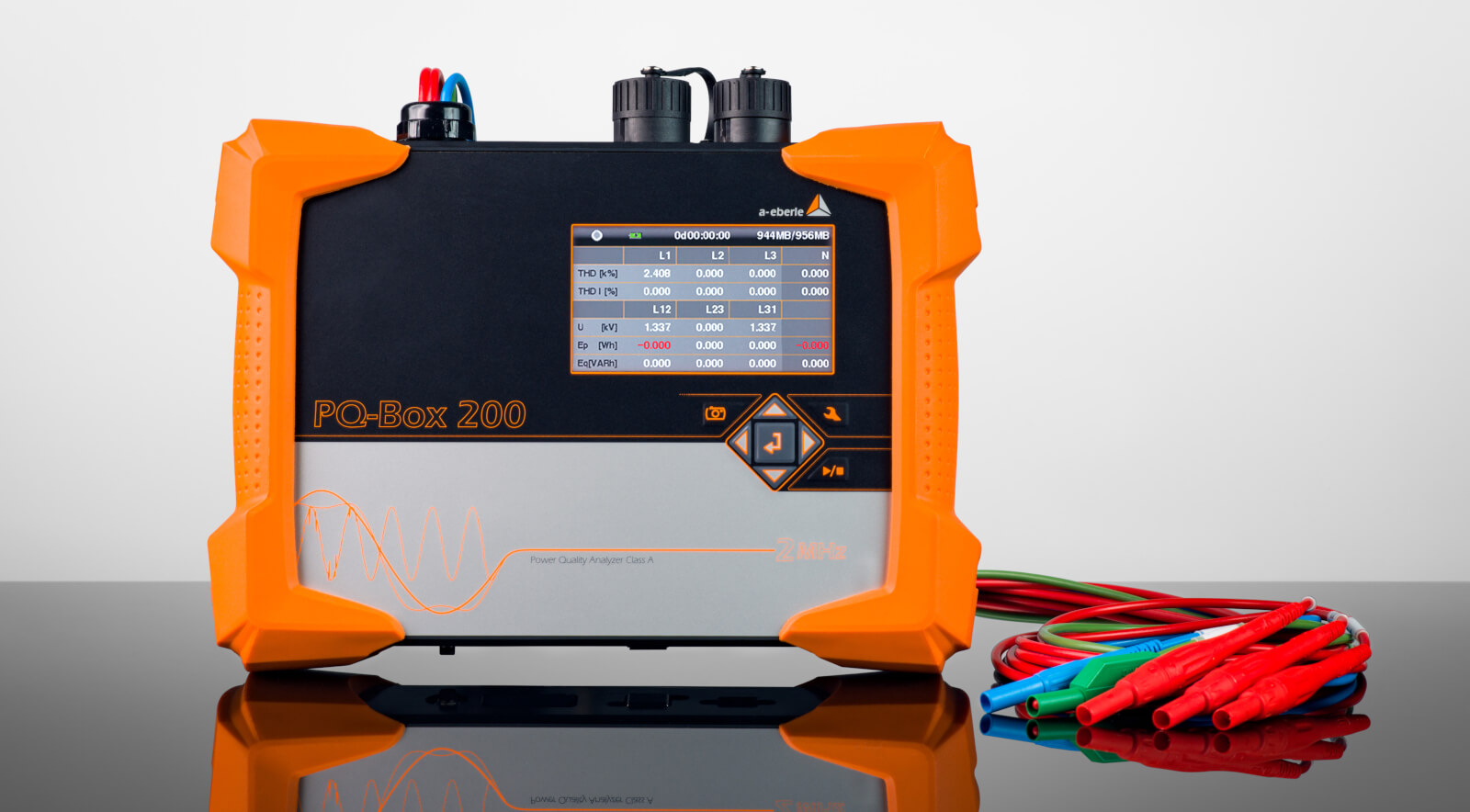
Our mobile power quality analyzers (PQ-Box 150, 200 and 300) offer a wide range of setting options to correctly measure the different types of power depending on the application.
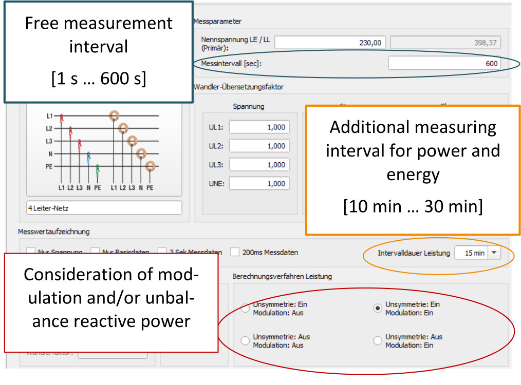
Selection of calculation methods according to application
While displacement and distortion reactive power are generally meaningful at every measuring point, the boundary conditions of the measurement and the position of the measuring point in the grid must be taken into account when measuring unbalance reactive power in order to obtain meaningful measurement data.
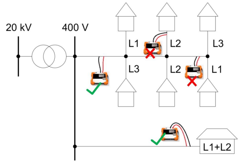
As an example, the following diagram shows a 400 V local network with a local network transformer, predominantly single-phase connected households and an industrial operation with a two-phase load (e.g. welding equipment).
The decisive factor for measuring unbalanced reactive power is therefore primarily the length of the line section that is loaded by the measured reactive power. When measuring in a residential area in which the individual loads are predominantly connected in single phase, very large unbalances occur. However, the measurable unbalance reactive power is not very meaningful here, as the load of the three-phase system changes at each nearby node and therefore no major section of the grid is loaded unbalanced.
In contrast, it makes sense to consider unbalance reactive power when measuring directly at the local network transformer or at long supply lines for unbalanced loads.
The measurement of modulation reactive power is highly dependent on the selected measurement interval. It therefore only makes sense to take this reactive power into account when calculating the collective apparent power if loads with periodically fluctuating power are present and the modulation frequency of the power fluctuation is known
Examples/concrete applications of power factor correction
Photovoltaic systems (PV systems):
- Power factor correction in PV systems with inverters is crucial for minimising the effects of capacitive or inductive reactive power generated by inverters. The inverter can be set in such a way that the reactive power is reduced to an optimum level.
Industrial systems with electric motors:
- In industrial systems, electric motors often generate inductive reactive power. Power factor correction through the use of capacitors or other compensation devices is important in order to increase energy efficiency and avoid overloads.
Inverters in energy technology:
- Power factor correction in inverters is about adjusting the settings so that the generated reactive power is optimized. This helps to minimize grid fluctuations and improve grid quality.
Private households with electric drives:
- Electrical household appliances can generate reactive power. Power factor correction in private households increases the power factor and optimizes the efficiency of the electricity grid.
Cables and transmission lines:
- When transmitting electrical energy over long distances, capacitive reactive power is generated in the cables. Choked reactive power compensators can improve the power quality and increase transmission efficiency.
Three-phase motors:
- In industrial applications with three-phase motors, power factor correction is important in order to optimize the power factor and minimize grid losses.
Series connection of reactive power compensators:
- In complex industrial networks, the series connection of compensation devices can be used to compensate for reactive power and ensure the stability of the system.
Power factor correction in private households:
- Power factor correction in private households is relevant for optimizing energy consumption and improving the overall efficiency of the electricity grid.
Choked power factor correction:
- Choked reactive power compensation is a specific method of minimizing the effects of reactive power in electrical systems.
Power factor correction is of great importance in various applications in order to improve the quality and efficiency of power grids, minimize grid losses and optimize the overall efficiency of electrical systems.