Earth Fault Compensation & Current Injection
Solutions for Varying Network Topologies
Earth Fault Compensation
Products
Current Injection and Pulsing
Products
What Is Earth Fault Compensation?
Earth fault compensation is a method of limiting the residual current in the event of an earth fault in an electrical power supply network. An earth fault is a fault in which one phase of the network is in direct contact with earth, which can lead to a significant residual current. The aim of earth fault compensation is to reduce this fault current to a minimum by using special chokes, so-called earth fault chokes or Petersen coils. A synonym for earth fault compensation is resonant star earthing, often referred to as an extinguished network.
Resonant star earthing is based on the principle that the inductance of the choke coil resonates with the capacitance of the mains. As a result, the capacitive current flowing in the event of an earth fault can be compensated, which greatly reduces the fault current or even brings it to almost zero. This form of earthing is particularly common in extinguished networks, where earth faults should only cause very low currents in order to ensure the safety and stability of the network.
An example: An earth fault occurs in a 20 kV medium-voltage network. By using a Petersen coil that is matched to the grid capacity, the fault current is reduced to such an extent that the grid does not need to be shut down immediately. The grid can continue to be operated and the fault can be rectified during planned maintenance without causing a grid failure.
Virtual Instruction Manual
Description of the Basic Approach for the Commissioning of the REG-DP(A)
MORE Information
AE Toolbox
The perfect supplement to arc suppression devices: freely adjustable project planning and parameterisation software
The AEToolbox works on a project basis and impresses with its range of functions and the versatility that the program offers.
Problems of Networks With Earth Faults Without the Use of Petersen Coils or Earth Leakage Coils (Earth Fault Compensation)
- Grids without earth fault compensation must be switched off in the event of an earth fault, resulting in a power failure
- If the network does not have earth fault compensation, high electrical currents flow in the ground at the point of the earth fault, which can cause high step voltages and touch voltages that are life-threatening for people and animals. If the permissible step and touch voltages are not complied with in the event of an earth fault (in a rigidly earthed system and usually also in an insulated system), the system must be switched off immediately
- The earth fault can cause sparks and arcs and thus fires.
- In insulated and compensated systems, the voltages of the healthy conductors increase in the event of an earth fault, which places additional stress on the insulation. Extra-high-voltage systems are therefore operated with rigid earthing, as the additional insulation effort would not be economical.
All Control, Measurement and Recording Tasks
„Around the Arc Suppression Coil“
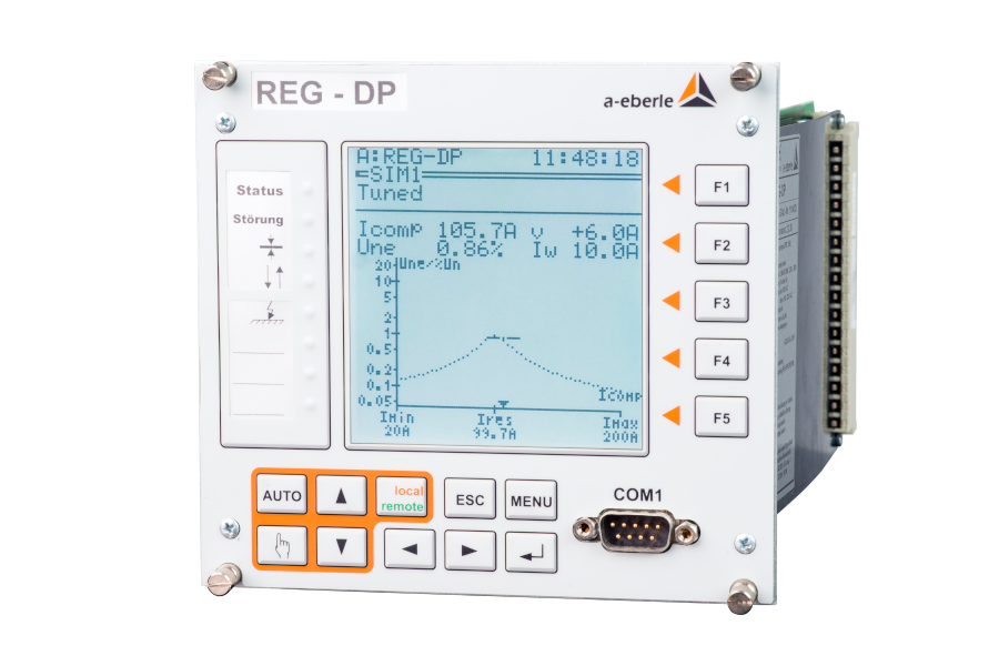
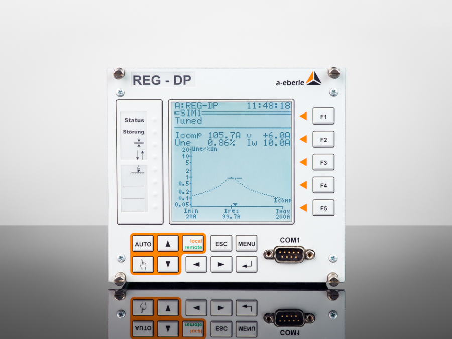
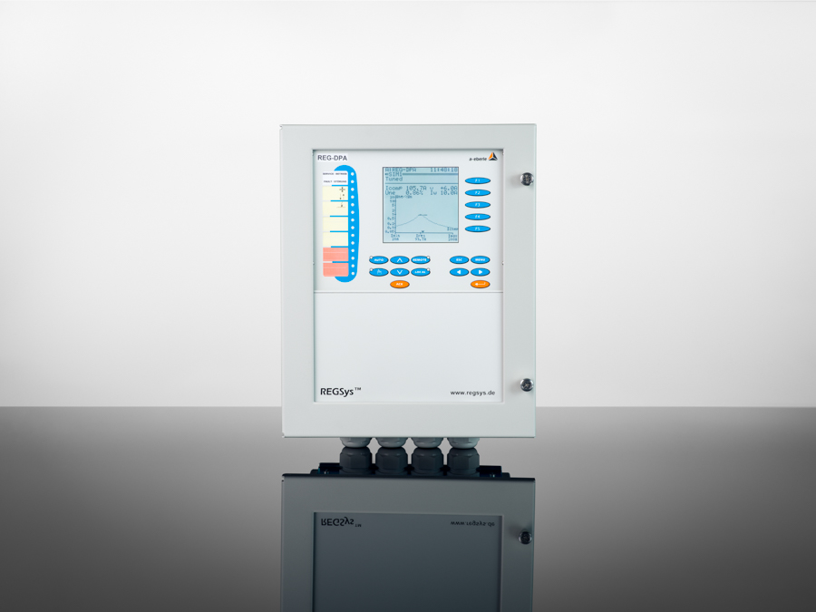
Our freely programmable petersen coil regulators REG-DP & REG-DPA are used in medium and high-voltage networks to regulate continuous, variable-under-load arc suppression coils (Petersen coils, also known as P-coils or E-coils). In addition, they can handle all other control, measurement and regulation tasks having to do with arc suppression coils.
The classic regulation process, i.e. searching for the resonance curve across the range of travel of the coil, can no longer successfully adjust the arc suppression coil in certain network situations.
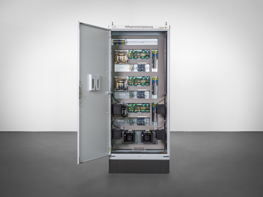
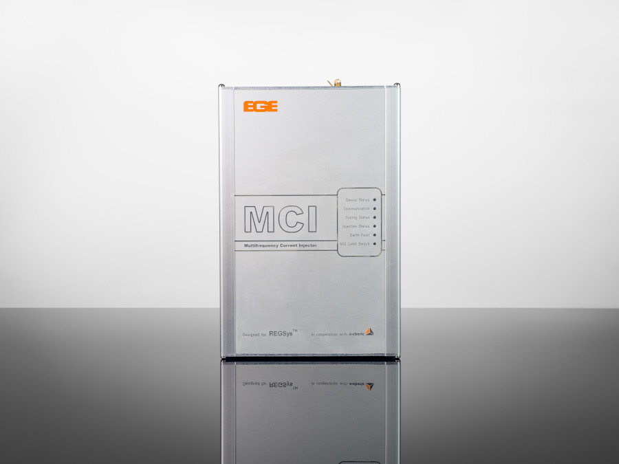
We have developed this current injection for the increasingly frequent cases where the zero-sequence voltage is highly disturbed or subject to extreme influences or where networks are highly symmetrical. The current injection creates a signal that is fed into the network via the auxiliary power winding of the arc suppression coil. From the network reaction, the combined REG-DP(A) and current injection are able to calculate a resonance curve despite the low or highly variable zero-sequence voltage.
Our Freely Programmable Petersen Coil Controllers
Reliable control in the event of an earth fault – proven a thousand times over and in use worldwide
How Is Earth Fault Compensation Calculated?
Petersen coils (also known as earth fault suppression coils) are used in medium and high-voltage networks so that in the event of a single-pole earth fault, the capacitive current across the fault location is compensated by an inductive current of approximately the same magnitude but in the opposite direction. For this purpose, the coil must be set to an inductive resistance XL in the healthy state of the system, which corresponds approximately to the capacitive resistance XC of the system.
Earth fault compensation in the three-phase system is shown in the following example analogous to the example for the isolated system. With full compensation by the compensation coil, the capacitive earth fault current Ice is fully compensated and in the event of an earth fault, the current at the fault location becomes IF=0.
Real grids are generally not fully compensated, but usually operated slightly overcompensated, as the zero sequence voltage is highest at full compensation (at the resonance point) and therefore one of the conductor voltages also assumes the most excessive value.
The degree of over- or undercompensation is indicated by the so-called detuning factor v.
v = (IL – IC) / IL
The resonance point and therefore the ideal tuning point for the earth fault suppression coil changes in real grids because the grid capacity changes due to switching. Automatic control of the coil is important to ensure that it is always tuned as appropriately as possible for the current grid status. This can be done with the REG-DP compensation coil regulator from A. Eberle. The REG-DP calculates the correct earth fault compensation automatically and continuously by measuring the resonance curve.
The required inductance of the coil is selected so that it resonates with the capacitance of the network. The resonance condition can be described mathematically by the following equation:
L = 1/ ω2 * C
Here, L is the inductance of the coil, C is the capacitance of the mains and ω is the angular frequency of the mains (ω=2πf, where f is the mains frequency).
In practice, the coil is set so that it compensates the grid capacitance as accurately as possible. This means that the resulting residual current in the event of an earth fault is minimal. The exact setting can also be adjusted on site to take account of fluctuations in the grid capacity.
In extinguished networks, it is particularly important that the earth fault compensation is calculated and set precisely, as the safety and stability of the network depend heavily on the effectiveness of the resonant star earthing.
This earth fault compensation achieves a high degree of operational safety, as earth faults can be compensated without immediate grid disconnection, which is particularly advantageous in complex and large-scale supply grids.
What Is (Short-Term) Low-Resistance Neutral Earthing?
Low-resistance star point earthing is a method of earthing the star point of an electrical network in which the star point is connected to earth via a resistor. This resistor has a relatively low value so that a high earth fault current flows in the event of a fault. This earthing method is used to ensure the protection of persons and systems in electrical distribution networks.
Short-term low-resistance neutral earthing refers to a specific operating mode in which the low-resistance earthing is only active for a short time after an earth fault occurs. This enables the fault to be detected and localized quickly, while the network maintains a high safety standard.
An example: An earth fault occurs in a medium-voltage network. The momentary low-resistance star point earthing is activated, generating a defined earth fault current that can be easily detected by the protective devices. After a short time, the low-resistance connection is disconnected to minimize the fault current and protect the system from further damage. The network can then continue to be operated in a higher resistance mode or with a different form of earthing.
The Low-resistance star point earthing method is typically used in networks where fast fault detection and rectification is required. The earth fault current is set high enough by the low-impedance resistor to reliably trigger overcurrent-dependent protective relays. The exact dimensioning of the resistor depends on the grid parameters, including the grid voltage and the earth fault current requirements.
A typical value for the resistance in a low-resistance star point earthing could, for example, be selected so that a current of several hundred amperes flows in the event of an earth fault. This high current ensures that the fault is detected quickly and the affected line is switched off.
Low-resistance star point earthing is often used in networks that are otherwise unsaturated star-point earthed to enable rapid fault detection. In these systems, short-term low-resistance star-point earthing offers the advantage that it only carries out earthing temporarily, which means that the advantages of other earthing methods, such as resonant star-point earthing, are not impaired.
In summary, low-resistance neutral earthing, and in particular short-term low-resistance neutral earthing, offers an effective method of earthing in electrical distribution networks that enables both rapid fault detection and a high standard of protection.