Short-Circuit and Earth Fault Indicators
Solutions for varying network topologies


Fit for the intelligent substations of tomorrow
Products
Quick Comparison: EOR-1DS vs. EOR-3DS
Find the right short-circuit and earth fault indicator for your application.
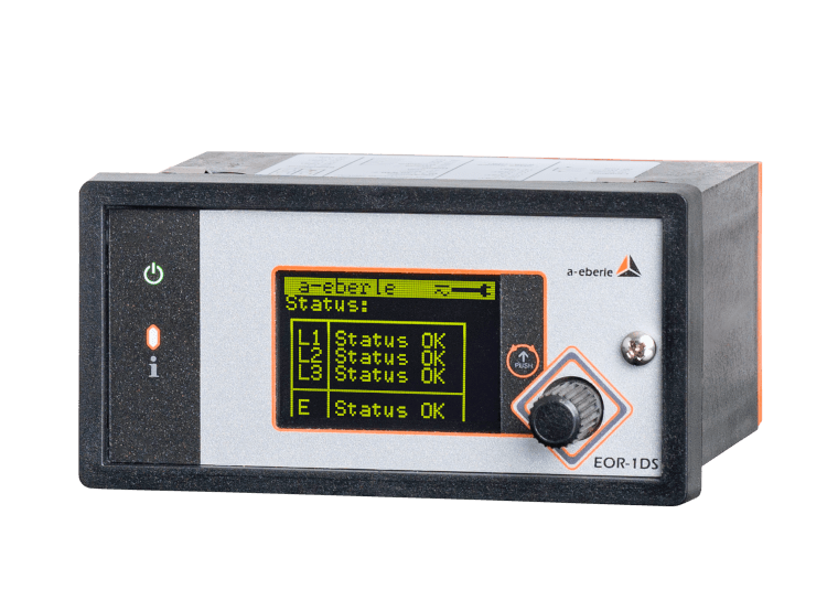
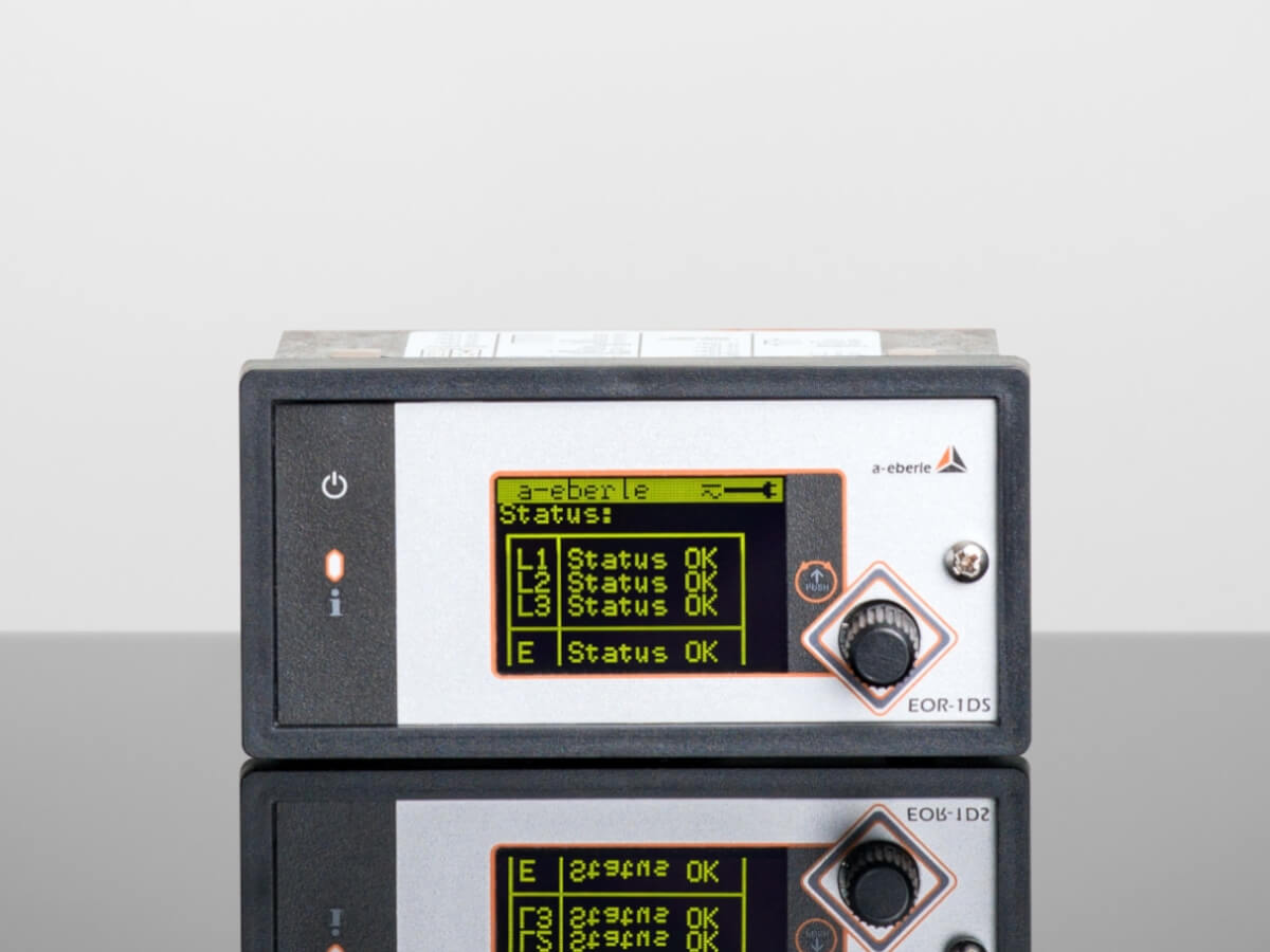
EOR-1DS
The fault indicator for
analog secondary substations
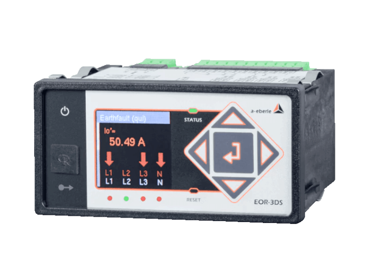
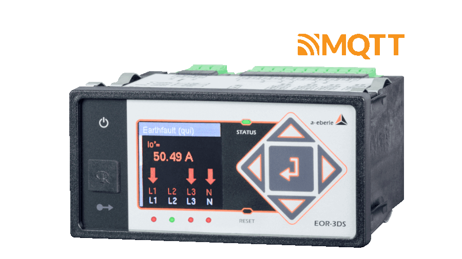
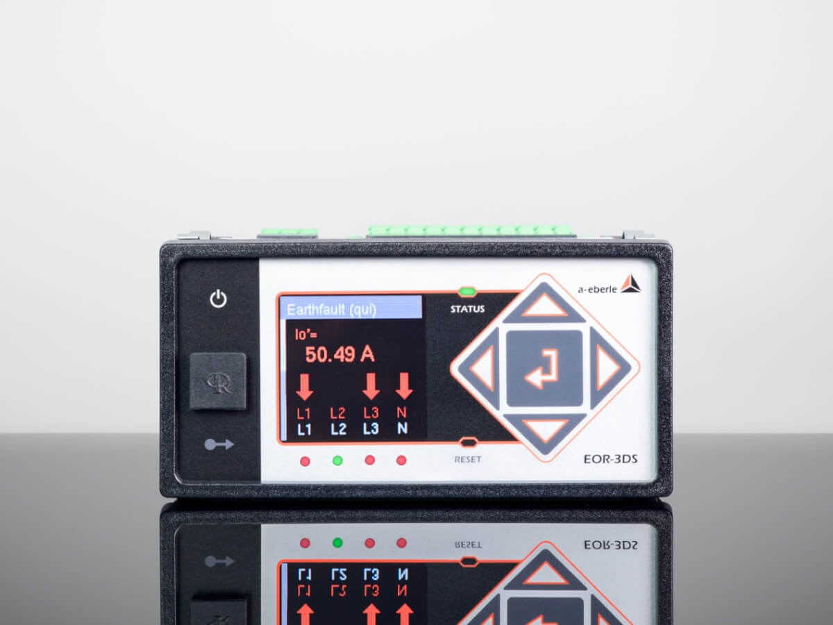
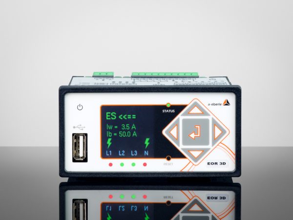
EOR-3DS
The fault indicator for
digital secondary substations
qu2 transient algorithm
Transient earth fault methodDirectional short-circuit and earth fault detection
Pulse location
❌
In preparation for EOR-1DS❌
In preparation for EOR-1DS❌
❌
Simple operation and parameterisation without software
❌
Extensive cyber security features✔️
Flash memory up to 32 GBCapacitive in parallel with VDS systems, low power sensors (two-wire technology) and classic transducers
Rogowski folding transducers, low power sensors (two-wire technology) and classic transducers
Modbus RTU
❌
❌
❌
❌
qu2 transient algorithm
Transient earth fault methodDirectional short-circuit and earth fault detection
Pulse location
Wattmetric method cos(φ)
Reactive power direction sin(φ)
qui-Method
Restriking faultsHarmonics method
Open setup as required with »AEToolbox« software
Certificate handling, user/role concept and encrypted connections
Extensive cyber security features✔️
Flash memory up to 32 GBCapacitive in parallel with VDS systems, Low power sensors (two-wire technology or RJ45) and classic transducers
Low power sensors (two-wire technology or RJ45) and classic transducers
Modbus RTU/TCP (Incl. “Modbus Master”)
IEC 60870-5-101 / 104, IEC 60870-5-103 Including Fault Records, IEC 61850 GOOSE, DNP 3.0
MQTT Management&Operations
MQTT IoT
Patch- and Devicemanagement via MQTT
Mass remote parameterisation and firmware updatesvia MQTT Management&Operations-function
Our short-circuit and earth fault indicators as an essential building-block
in substations & secondary substations
Our short-circuit and earth fault indicators make it possible to combine the advantages of different location methods. This makes it possible for the first time to prioritise and weight the methods in order to perfectly match them to the respective application.
This combination makes our devices particularly suitable for use in secondary substations. Of course, these advantages also come into play directly in the substation.
News from the Productgroup
EORSys – News

Product innovation
Product discontinuation: Profibus-DP in the types B01 & B02 as of 15.05.2024
3. June 2024
Profibus-DP in the types B01 & B02 is currently scheduled for product discontinuation.[…]
Read more
General Knowledge
The Future of the Distribution Grid: Focus on Digital Secondary Substations
13. May 2024
In this technical report, Gerald Jacob (Product Manager »EORSys«) uses a specific example to illustrate how distribution system operators can meet the challenges of energy transition in the medium and[…]
Read more
General Knowledge
Earth fault explained – basics and functions of an electrical phenomenon
6. March 2024
Everything you need to know about earth faults – from the basics, causes and examples to the consequences. Find out more in this article about earth fault clearing, compensation, location and the benefits[…]
Read more
General Knowledge
Ready for the smart grid of the future?
6. March 2024
All information about smart grids/intelligent power grids, the technology behind them, advantages, disadvantages, challenges and current distribution.[…]
Read more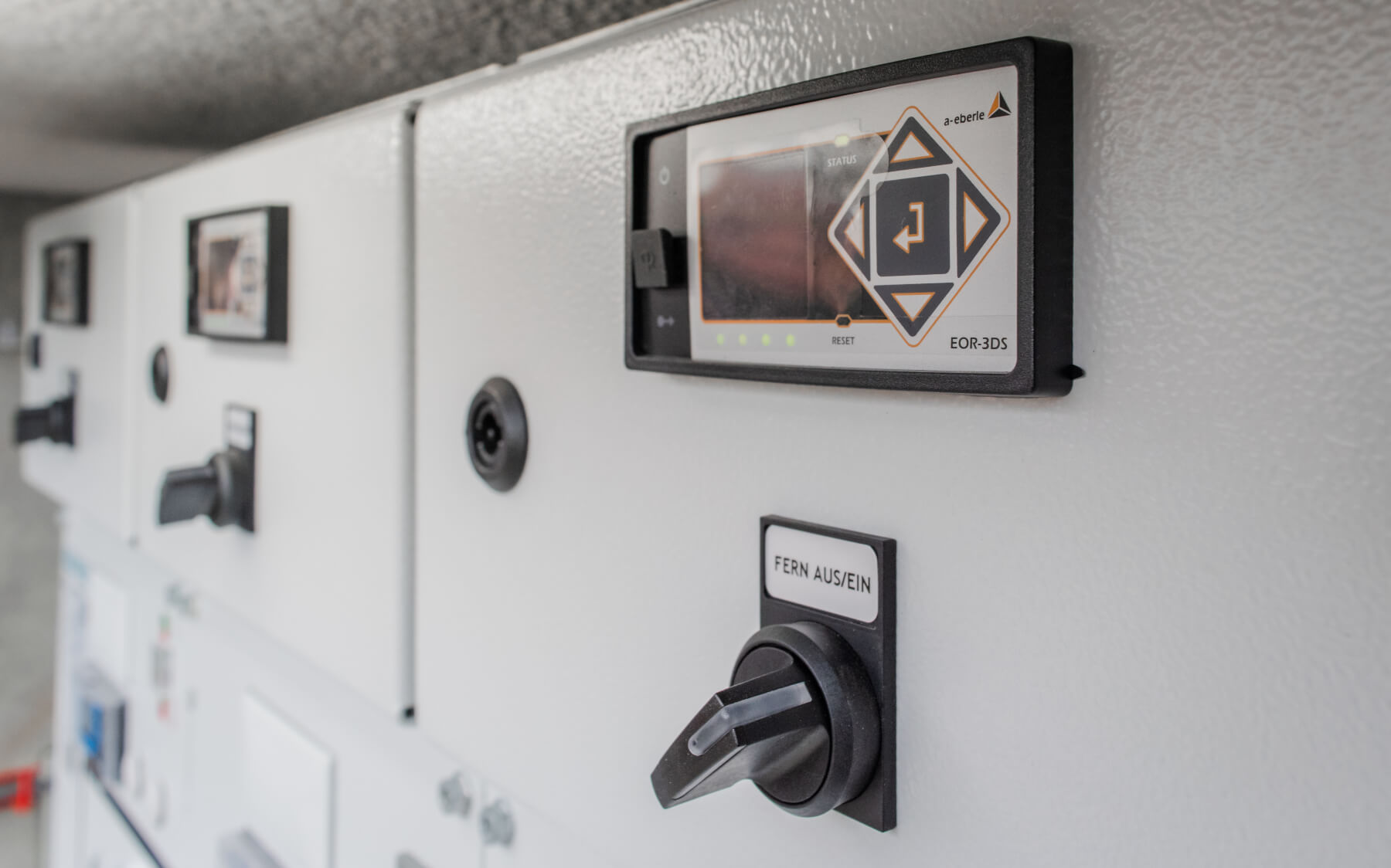
Special Publication
Cost Efficient Management of Digital Secondary Substations: Earth Fault Indicator EOR-3DS as Digitisation Unit for Secondary Substations
11. August 2023
Digital secondary substations are becoming a key element for distribution system operators in terms of automation, monitoring, and efficient operations of their networks. Read this technical report about[…]
Read more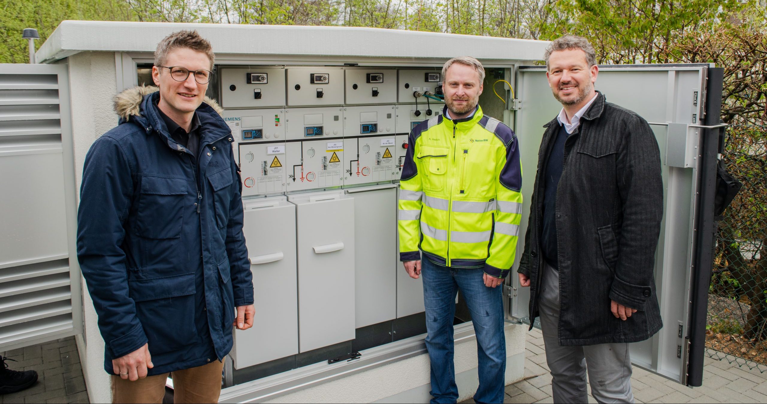
Blogpost
Kick-off for Mass Rollout of the Digital Local Network Station at »Netze BW«
31. July 2023
Our product manager Gerald Jacob (»EORSys«) with a short Q&A at the official kick-off event of the digital secondary station »FFU 2.0«.[…]
Read more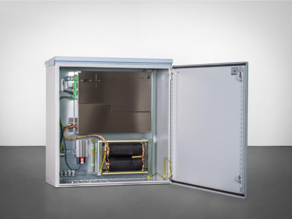
Product innovation
Product discontinuation: Current Injection CI, as of 30.06.2023
14. July 2023
The Current Injection CI is currently scheduled for product discontinuation.[…]
Read more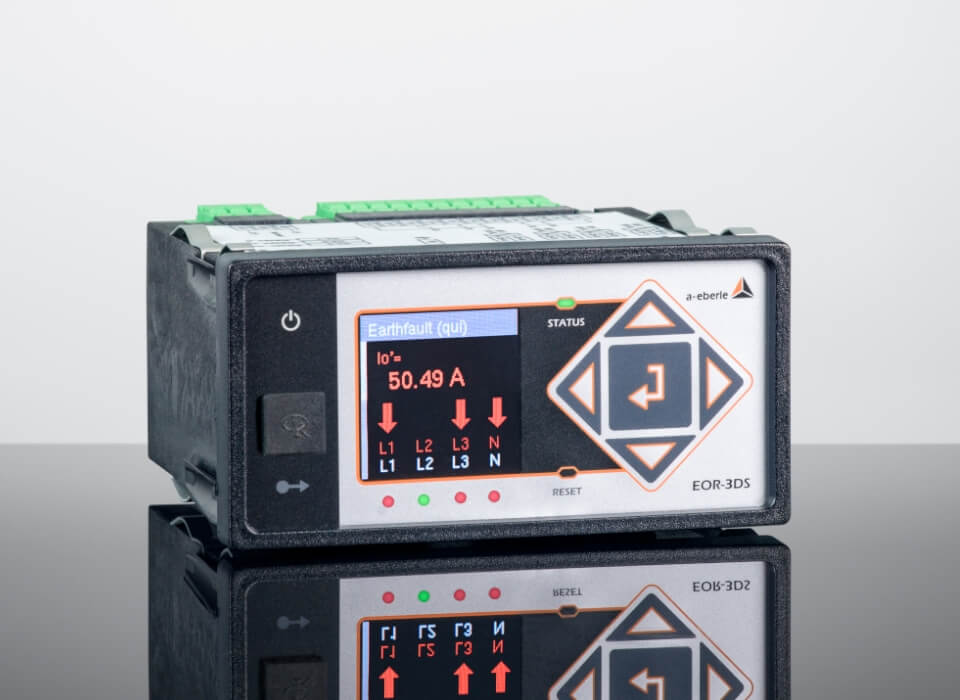
Blogpost
Brand New: Short-Circuit and Earth Fault Indicator EOR-3DS Released on 27.03.2023
27. March 2023
New combined earth fault and short circuit indicator EOR-3DS: AVAILABLE FOR ORDER NOW[…]
Read more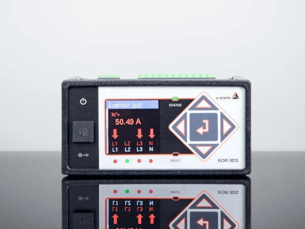
Product innovation
Product announcement: Short-circuit and earth fault indicator EOR-3DS released on 27.03.2023
24. March 2023
New combined earth fault and short circuit indicator EOR-3DS: AVAILABLE NOW[…]
Read more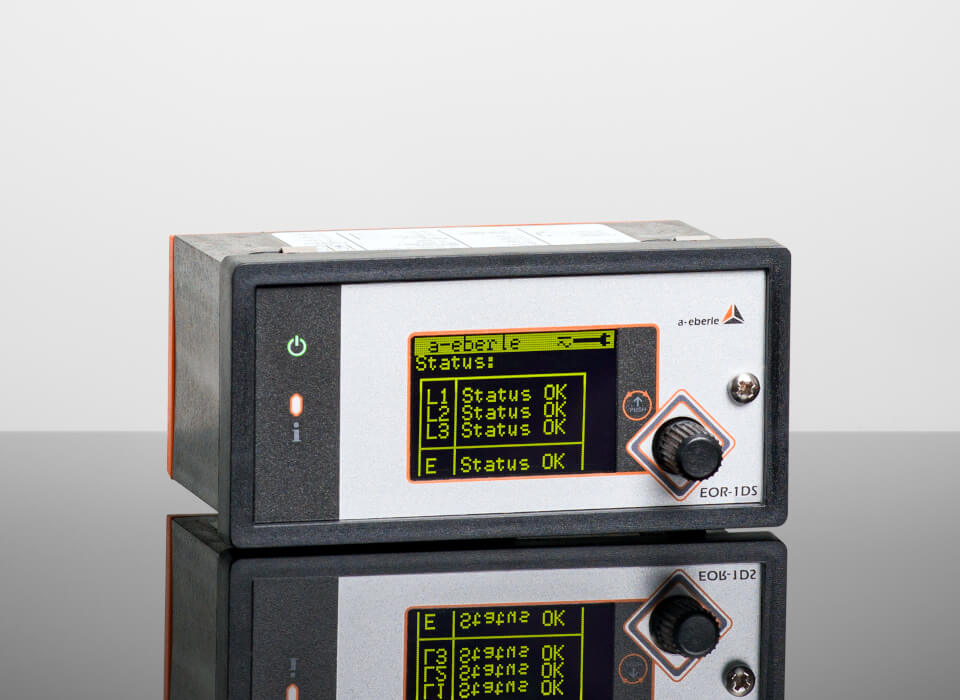
Blogpost
Product Announcement: Short and Earth Fault Locator EOR-1DS Released 05.08.2022
23. August 2022
We are pleased to inform you that the product »Combined Earth Fault and Short Circuit Indicator EOR-1DS« is officially released as of today. […]
Read more
Product innovation
Product Announcement: Short and earth fault locator EOR-1DS released 05.08.2022
23. August 2022
Combined earth fault and short circuit indicator EOR-1DS: AVAILABLE NOW![…]
Read more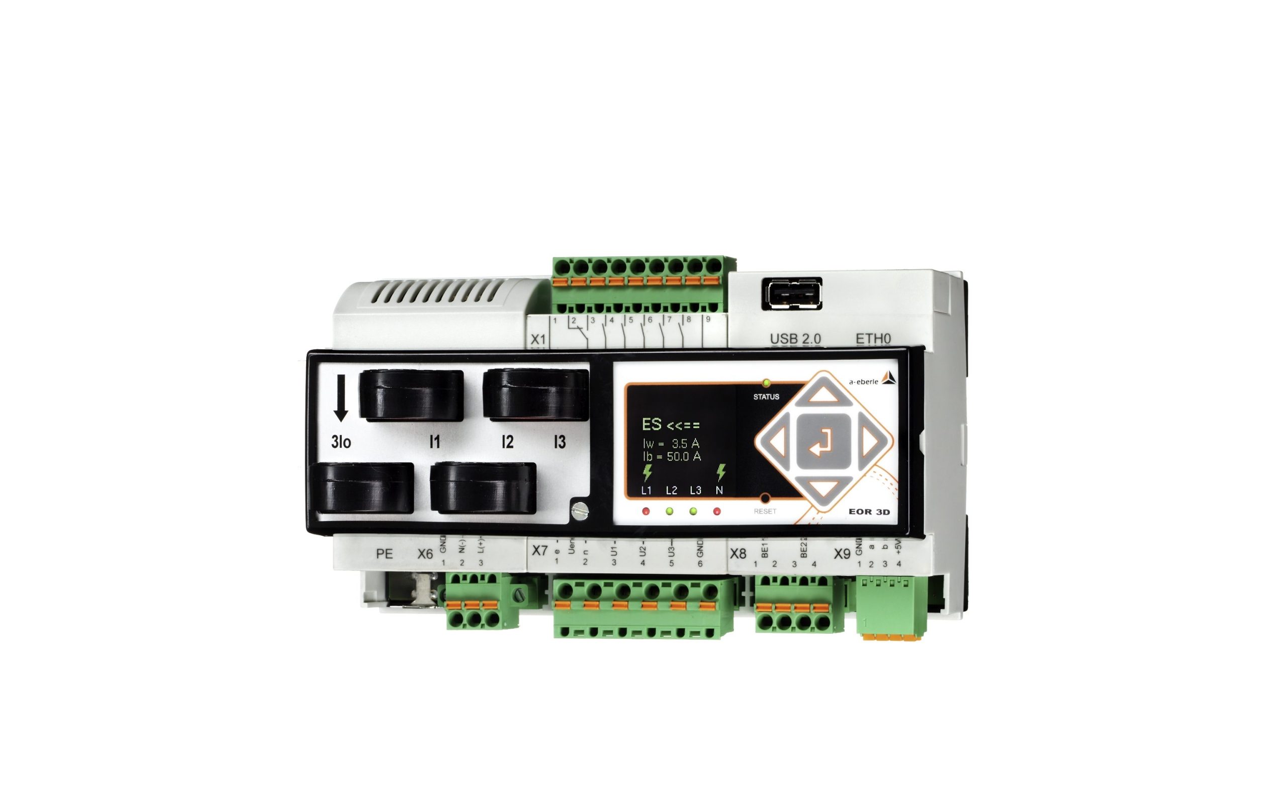
Product innovation
Product discontinuation: DIN rail housing EOR-3D (characteristic B02) until 30.06.2020
12. April 2022
The EOR-3D with characteristic B02 (article numbers: 119.8500 to 119.8584) is currently planned for product discontinuation.[…]
Read more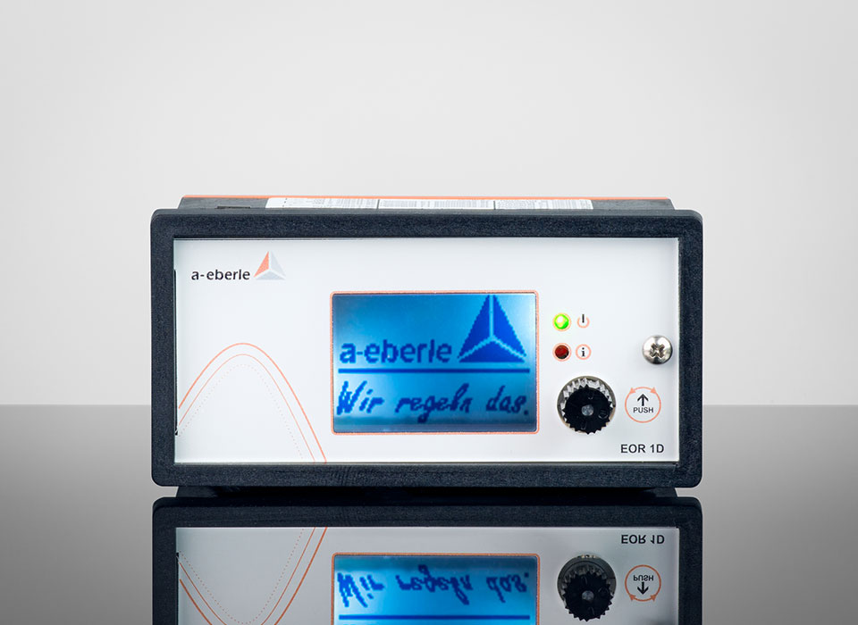
Product innovation
Product discontinuation: Short-circuit and earth fault indicator EOR-1D, as of 31.03.2022 (successor will be EOR-1DS)
12. April 2022
Read more
Product innovation
Product care / follow-up device: EOR-3D B01 & B03 become the substantially optimized EOR-3DS
12. April 2022
The EOR-3D with feature B01 or B03 (part numbers: 119.80xx to 119.82xx.xx) is currently planned for product discontinuation.[…]
Read more
Info letter
Info Letter No. 21: The influence of the contact resistance at the earth-fault location on the zero sequence voltage UEN in compensated networks
7. September 2021
The earth fault in compensated networks is usually presented without a contact resistance at the fault…[…]
Read more
Info letter
Info Letter No. 20: Capacitance of conductors
7. September 2021
In the conductors of electrical power supplies, a distinction is made between the operating capacitance… […]
Read more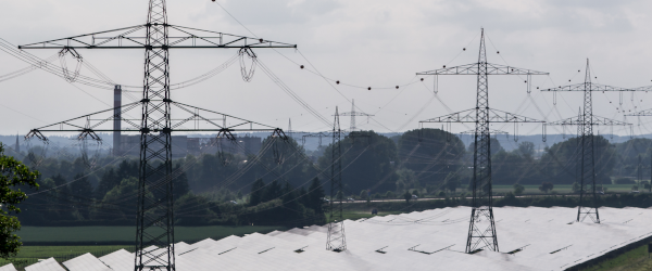
Info letter
Info Letter No. 18: Transient relay for high resistance, intermittent and recurrent earth faults (Part 2)
7. September 2021
Figure 3 can also be used for the determination of static earth faults. In an isolated network the entire…[…]
Read more
Info letter
Info Letter No. 17: Transient relay for high resistance, intermittent and recurrent earth faults (Part 1)
7. September 2021
The statistics show that earth faults constitute a large proportion of network faults. Conventional relays…[…]
Read more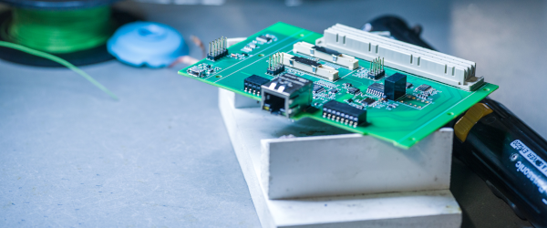
Info letter
Info Letter No. 15: Earth fault location using the harmonic procedure (Part 2)
7. September 2021
For the study of the behaviour of the harmonic currents and voltages in the compensated network, at…[…]
Read more
Info letter
Info Letter No. 14: Earth fault location using the harmonic procedure (Part 1)
7. September 2021
For the following considerations a network with three outputs and an earth fault in line 1 in output…[…]
Read more


