Abstract
Digital secondary substations (DSS) are becoming a key element for distribution system operators (DSO) in terms of automation, monitoring, and efficient operations of their networks. The DSS will be a vital element of the future actively operated smart grid and thus DSOs as well as manufacturers will have to face new challenges such as large-scale roll-outs of networked devices distributed over the whole power grid.
Compared to classical offline devices, connected devices demand more attention in terms of the associated management and operation processes. For example, a continuous patch management over thousands of devices needs to be realized for maintaining proper IT security standards and for providing functional updates. Manual processes cannot cope with the related huge amounts of tasks in an acceptable amount of time and in an economic way.
Netze BW has therefore defined a new management and operations architecture together with a standardized device for ring main units (RMU), the process interface and detection unit (PIDU).
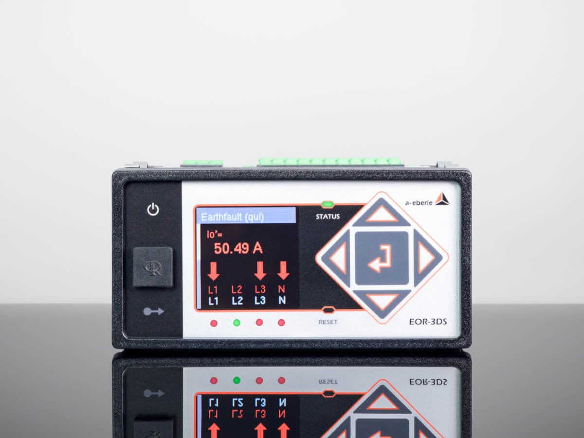
When used as a PIDU in the digital secondary substation, our new EOR-3DS fault indicator combines classic earth fault and short-circuit location with the necessary digital interface functions. This turns the short-circuit and earth-fault indicator into a completely new class of device: the EOR-3DS as digitisation unit for secondary substations.
This paper will first describe how the operating costs per secondary substation can be reduced with the help of a modern management and operation system. Secondly, a new device for RMUs, the PIDU, is introduced.
Introduction
The main challenges with large scale roll-out are well known in the IT world. The OT world is still less accustomed to solutions that help manage the challenges currently arising in MV/LV smart grids.
- The management and operations system enables an efficient, scalable and cost efficient roll-out of secondary substations. It allows the DSO to reduce the operating costs per secondary substation during the ongoing roll-out and later during operations.
- Therefore, new powerful devices like PIDUs with the EOR-3DS as the digitisation unit are necessary to fulfil the new requirements for digital secondary substations:
- A large number of devices need to be managed and deployed efficiently
- Hardware performance must be future proof
- Must fit into the limited space requirements within ring main units
- Support for modern communication protocols
- Integration of distributed functionalities into one device (e.g. fault detection, control,
measurement) - Implementation of security features [1]
- Connectivity for Low-Power Instrument Transformer (LPIT) sensors
System Architecture
It is widely accepted that efficient management of future distribution grids will entail a large number of interoperating, intelligent automation devices, most likely with a rising level of autonomous operation [2].
At Netze BW it is estimated that approx. 10-20% of all projected new secondary substations will need to be digital in nature and thus connected via a networking connection.
Based on the corresponding number of several thousand networked devices in the grid, manual management & operations processes quickly hit an acceptable time and resource limit. Also, as security updates of devices are critical, short-term measures are vital to ensure the continued IT security in the grid. Here, best practices and established procedures for mass firmware roll-outs known from sectors such as telecommunications, industry [3] or the smart meter environment [4] can serve as an architectural blueprint also for the distribution grid.
From the point of view of technological implementation, devices that have an integrated update function are widely established today in the areas of controllers, sensors, actuators and communication devices. Only through updates is it possible to implement incremental functional developments efficiently when a large device base is present. Functional improvements mainly stem from two different subjects:
- Necessity to implement future grid-related functional improvements (e.g. smart automation)
- Necessity to comply with non-functional requirements such as logging, data traffic analytics, digital authentication procedures, etc.
In the past, any functional as well as any non-functional device improvement has led to the need to install new devices on site, to replace existing devices in the field or, if device capabilities allow for this, to update them manually. In order to realize improvements efficiently and without interruptions in grid operation, a new holistic system architecture is needed.
To this effect, Netze BW has developed a new operating standard in second generation for remotely reported and controlled secondary substations, called FF-U 2.0, in which the EOR-3DS is used as a switching and signalling centre.
At its core, this operating standard enables all devices to be rolled out and operated in a highly scalable manner via an adequate management platform.
At the same time, measurement data and operating states of sensors are made available to various data sinks (called “Data User” in Figure 1) via an independent data platform using an MQTT broker (called “Broker” in Figure 1). Data storage is the responsibility of the data recipients themselves, since different time series are of interest depending on different task. Data brokers are kept completely separated from the operating platform itself.
A uniform namespace (UNS) was defined in order to be able to provide data for different data users and to be able to standardize it on the secondary substation side. Due to better scalability of the overall system architecture, data collection is characterized by a much higher level of flexibility and granularity when compared to traditional SCADA systems.
Traditional SCADA is also used, but it acts independently and remains completely untouched by the new FF-U 2.0 data broker mechanism. Figure 1 shows a schematic overview of the overall system architecture.
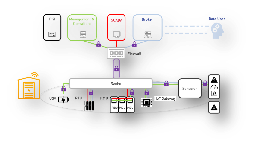
In addition to classic measured values such as transformer oil temperature, door contact status or current loading values connected low voltage, sensors also include power quality parameters. Thanks to the modular design, it is possible to collect additional measured variables at any time, process them locally and send them to the central broker. In the medium-voltage system, so-called process and detection units (PIDU) are also used, which enable fault location and combine measured values and control functionalities. They thus make an important contribution to transparency in the medium-voltage level. Additional sensors can be flexibly integrated via the IIoT gateway.
Role of the Management and Operations Plattform (M&O)
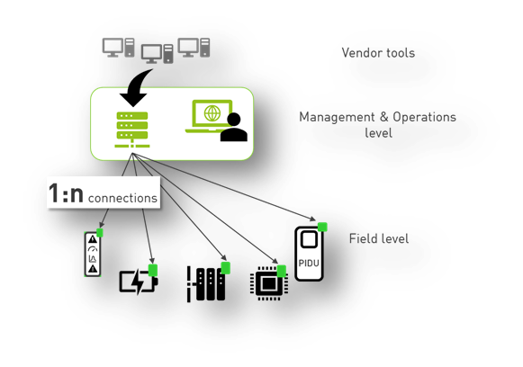
A centralized device and patch management is absolutely vital to warrant a highly scalable system adequate for grid-wide rollout and for IT-secure operation. From the user’s point of view, a uniform, standardized platform for all devices employed within FF-U 2.0 was aspired.
A particular challenge in the implementation of this platform is posed by the need to integrate multiple device manufacturers. Achieving a homogeneous integration across manufacturer boundaries significantly reduces the training effort for the operating staff, since then only a single unified platform has to be managed. Unification is achieved by imposing a standardized command interface between the central platform and all field devices.
Furthermore, the M&O platform allows to schedule processes on many devices in parallel. This includes, for example, the tasks of rolling out patches or querying device information. Still, different manufacturers are allowed to use different proprietary device files and metadata coming from their individual vendor-specific tools. Unification is obtained by making all the different files and device resources available to the M&O platform via automated data synchronization mechanisms.
Figure 2 shows the corresponding logical view of file exchanges between the central platform and devices from different manufacturers.
It is of particular importance to note which use cases are to be fulfilled by this platform. There are three different categories:
- Operations
Device monitoring, diagnostics, predictive maintenance, troubleshooting. - Management and inventory
Stockpiling spare parts, device substitutions, documentation for the information security management system (ISMS) when operating critical infrastructure according to the ISO27001 standard [5], accurate bookkeeping of the number and type of assets installed in the field. - Service
ISMS updates, security updates, device configuration changes, functional device improvements, device commissioning, device factory acceptance testing.
Cost Considerations
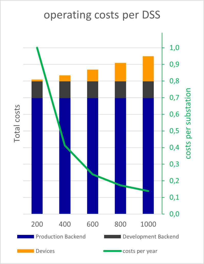
Total costs for operating the M&O architecture are heavily influenced by the initial costs for the IT-Backend (Figure 3, shown in blue) as well as by the initial costs for the test environment (Figure 3, shown in gray). As the roll-out progresses, those initial costs are divided by the increasing number of connected DSS. A much smaller variable cost component (Figure 3, shown in orange) consists of the service-level prices for the installed devices. These costs slightly increase with the increasing number of installed DSS.
The green line in Figure 3 makes it clear that the individual total costs of ownership and operation per DSS decrease significantly as the number of DSS in the grid increases. At a quantity of 1000 DSS installed, the corresponding cost is only 15% of the initial cost per DSS at the start of the rollout.
The green line in figure 3 makes it clear that the individual total costs of ownership and operation per DSS decrease significantly as the number of DSS in the network increases. At a number of 1000 DSS installed, the corresponding cost is only 15% of the initial cost per DSS at the start of the rollout.
In summary, we argue that a central M&O platform is a sensible investment from the point of view of scaling. A design as a modular platform also ensures the future viability of the solution, while the aspect of manufacturer independence reduces the complexity for end users and further increases scaling effects. In addition to the central platform, the ability to update the software of all field devices is a mandatory factor in order to be able to guarantee the secure operation of an ever-growing fleet of grid devices.
Process Interface and Detection Unit (PIDU)
Earth-fault and short-circuit indicators (EF/SC indicators) are commonly installed in most medium-voltage switchgears nowadays, in order to be able to quickly assess the fault location in the event of single-phase or multi-phase faults.
Many distribution grid operators connect EF/SC indicators to a control center via a standardized IEC protocol such as IEC 60870-5-104, ensuring central messages recording and evaluation.
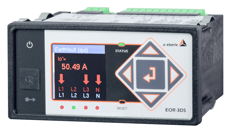
The EOR-3DS used in the FF-U 2.0 digital local network station also fulfils a number of other features in order to meet the requirements of the remotely reported and remote-controlled secondary substations of the future and also to still be able to manage the number of devices in the field. These functional extensions turn a pure short-circuit and earth fault indicator into a completely new class of device: the EOR-3DS as digitisation unit for secondary substations.
SCADA
In addition to a classic SCADA protocol such as IEC 60870-5-104 oriented towards the control center (Figure 1, red path), a FF-U 2.0-type PIDU features two additional protocols based on the MQTT standard, which run inside the device in parallel.
The “Management & Operations” feature (Figure 1 green path, “M&O” for short) can be used to carry out parameter and firmware updates with the help of a central M&O platform. Such updates can take place as fleet updates on a large number of devices at the same time or staggered over time. In addition, additional PIDU parameters such as heartbeat, CPU load, batch numbers, etc are monitored via the central IoT software.
As stated also above, a quota of approx. 10-20% digital secondary substations is needed for obtaining adequate network transparency and sufficient remote control capability in a typical distribution grid. In absolute numbers, this can mean a device fleet of several thousand PIDUs in larger utilities, clearly underlining again the need for a central M&O platform.
Via a separate IIoT path (blue path in Figure 1), measurement data and EF/SC messages of all nodes are sent to a central broker for further evaluation in real time. This monitoring function opens up new possibilities for various departments of the distribution network operator, such as asset management or network planning.
The role of FF-U 2.0´s PIDU is filled by an EOR-3DS from A. Eberle GmbH & Co. KG. This device is able to provide all three protocols on one Ethernet interface. Alternatively, it is possible to divide data up between two separate physical network connections, e.g. using one network for M&O and SCADA and a second and separate network for IIoT.
Commonly used physical cross-connections of binary signals inside the switchgear are obsolete in this concept, due to ubiquitous network connectivity. All signals are processed directly in their field of origin by the associated PIDU and are then transmitted via Ethernet.
Remote Switching
Load breaking switches and grounding switches of the individual cable and transformer feeders are recorded via PIDUs and reported as double messages. In addition, the load-break switches of all cable fields can be remotely controlled via the IEC 60870-5-104 protocol. Based on the free programmability (PLC functionality) of the PIDU, various advanced load-break switching and monitoring functions were implemented.
As a result, erroneous switching requests are ignored based on fault/intermediate position and feedback time monitoring of the load-break switch as well as of its motor drive.
Measurement and Fault Indication
As measurement data captured by the PIDU is used in the SCADA center as well as for additional asset management and network planning analytics, a high level of accuracy is required. By combination of low-power sensors with measurement class 0.5 according to IEC 61869 together with PIDUs of class 0.5, a high overall accuracy of <1.0% can be achieved across the measurement chain.
In the FF-U 2.0 standard cable connection bushings with integrated low power instrument transformers from Siemens (SIBushing) are used, offering clear advantages in measurement accuracy over conventional inductive solutions. For fast, simple and error-proof commissioning, SIBushings are equipped with color-coded RJ45 connector cables and are plugged into the respective color coded RJ45 jacks of the PIDUs.
All PIDUs receive individual sensor configuration files containing all necessary calibration factors, a step that is already taken during assembly in the switchgear factory. This enables the required high level of measurement accuracy already ex works, without the need for further parameterization or corrective measures by the operator.
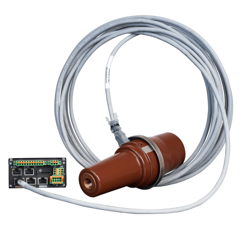
Due to an integrated PT100 element in every SIBushing, the PIDU is also able to accurately determine bushing temperature for each phase individually. This feature enables bushing sensor condition assessment and corresponding predictive maintenance schemes.
The high measurement accuracy of SIBushing and PIDU, both for currents and voltages, enables the usage of the wattmetric earth fault location method, while doing away with the need for expensive core balanced current transformers (CBCTs). Additionally the robust transient qu2 algorithm as well as the pulse location methods are used.
IT-Security
All communication paths in FF-U 2.0 standard are fully Ethernet-based. No legacy protocols such as Modbus RTU are employed anywhere.
In order to ensure adequate IT security, each PIDU is pre-equipped with individual manufacturer certificates signed by the distribution grid operator and is delivered with an activated firewall. This means that after delivery by the manufacturer A. Eberle, PIDUs can neither be changed manually via the local user interface nor via the manufacturer’s AEToolbox configuration software without proper authentication.
After the PIDU is installed in the grid and the DSO´s own communication network, a valid operator´s certificate is installed on the PIDU. This step enables the usage with the central M&O platform.
Any settings of the PIDU can then only be changed via this central platform, preventing unwanted manipulation of device settings along the supply chain.
In order to ensure an effortless change of operator certificates, up to five different certificates can be loaded onto the PIDU in addition to the existing manufacturer certificate. Furthermore, initial registration in the network of the distribution network operator is protected by a 2-factor authentication (2FA) using a QR code printed on the device.
Outlook
Due to the PIDU´s hardware performance, the distribution network operator is in a position to improve the devices with extensive functional and non-functional upgrades over their life-time.
Corresponding examples comprise of medium voltage level power quality measurements, advanced edge intelligence features in each field or new earth fault detection algorithms. Also flexible, automated load shedding scenarios for outgoing feeders overloaded by e-mobility are possible.
Non-functional extensions lie in the area of IT security patches and operating system upgrades as well as communication protocol updates. This would enable the rollout of innovations in the area of MQTT/IIoT/M&O protocols, or even the inclusion of IEC 61850 MMS if needed.
Conclusion
Maintaining a high level of network availability in the electrified society of the future creates the need for advanced monitoring and control functions in our power distribution grids.
The FF-U 2.0 secondary substation operation architecture presented in this paper represents a future-proof solution for meeting these requirements even in grids heavily affected by the energy transition and facing the shift to decentralized generation.
Regarding its remote monitoring and remote control capabilities, FF-U 2.0 clearly exceeds traditional solutions and conventional substation devices available on the market today. Its main focus lies on providing a highly scalable system and enabling simple processes on a future-oriented platform for the DSO.
Thus, a central M&O platform is essential for the efficient and economical rollout of updates, as well as for efficient operation of thousands of intelligent devices.
The usage of PIDUs as part of the FF-U 2.0 ecosystem extends the purpose of conventional short-circuit and earth-fault indicators beyond pure fault detection. The range of possible additional functions is significantly expanded due to individually remote controllable cable fields in the medium-voltage switchgear and due to high-precision medium voltage measurements.
PIDUs enable a simultaneous connection to the control center, to a central management platform and the disposal of all data to an additional MQTT broker. Furthermore, PIDUs reduce the wiring effort and complexity within the secondary substation and simplify the commissioning process.
Security features such as certificate-based authentication and integrated firewall functionalities known from the IT environment are implemented to protect the OT communication connections at network level. Remote firmware updates are possible, thus enabling both functional and non-functional upgrades without the need of expensive hardware upgrades.
The digital secondary substations will play a key role in enabling highly flexible yet stable distribution grids. The corresponding functional evolution in the grid is enabled by providing a future proof hardware base and extensive edge computing capabilities through the employed PIDU devices.
Official Roll-Out: The EOR-3DS in the Digital Secondary Substation »FF-U 2.0« at Netze BW GmbH (Large German DSO)
Q&A With Product Manager EORSys, Gerald Jacob (A. Eberle GmbH & Co. KG)
References
- “Whitepaper: Requirements for Secure Control and Telecommunication Systems”, BDEW, Berlin, Germany 2018
- “VDE Impuls Systematisierung der Autonomiestufen in der Netzbetriebsführung”, VDE ETG Germany 2020
- “Security Architecture for Open Systems Interconnection For CCIT Applications – Recommendation X.800”, ITU International Telecommunications Union, 1991
- “Das Smart Meter Gateway – Cyber – Sicherheit für die Digitalisierung der Energiewirtschaft”, Bundesamt für Sicherheit in der Informationstechnik, Germany
- “ISO/IEC 27001:2022 Information security, cybersecurity and privacy protection — Information security management systems — Requirements”, International Organization for Standardization, 2022
Authors
Andreas HETTICH, Netze BW GmbH, Deutschland, a.hettich@netze-bw.de
Fabian ZEHNER, Netze BW GmbH, Deutschland, f.zehner@netze-bw.de
Gerald JACOB, A. Eberle GmbH & Co. KG, Deutschland, gerald.jacob@a-eberle.de
Dr. Christian RÜSTER, A. Eberle GmbH & Co. KG, Deutschland, christian.ruester@a-eberle.de