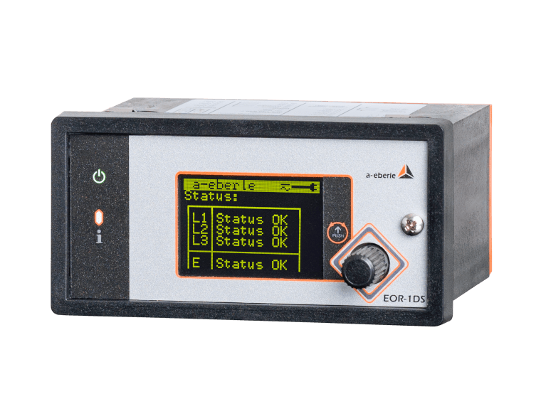


The EOR-1DS is a combined earth fault indicator and short-circuit indicator for fast fault location, helping to reduce downtime. It supports grid operations, engineering, and service teams with clear information for safe switching operations and rapid restoration of supply.
Typical applications:
- Retrofitting existing local distribution substations for earth-fault and short-circuit detection
- Non-directional and/or directional fault location for single-phase earth faults, short circuits or short circuits to earth.
- Narrowing down the fault location to individual feeders within the grid area
- Recording events and fault records for internal clarification and documentation
This device is suitable, if:
- The fault location needs to be narrowed down quickly in order to reduce downtime
- Field teams require clear information for safe fault localization
- Earth-fault and short-circuit indications need to be reported automatically to the central control system
- Additional measurement values from deeper within the grid are required with high measurement accuracy
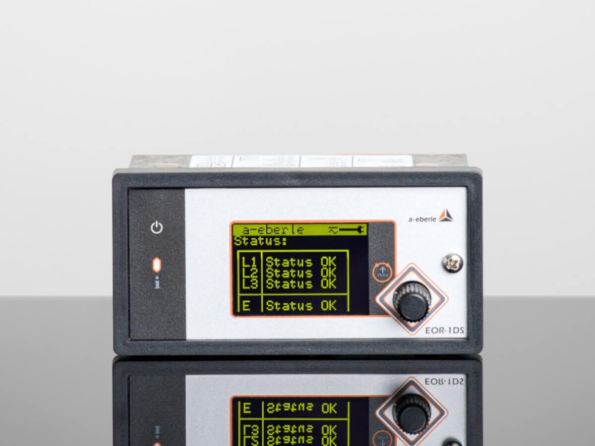
Earth Fault and Short-Circuit Indication in a Single Device
EOR-1DS
The »EOR-1DS« is a compact, combined earth fault indicator and short-circuit indicator that supports all essential fault location methods. The device was specially developed as a cost-effective alternative to comparable solutions on the market. The device can be used as a non-directional short-circuit and earth fault indicator (pulse location) with the supplied Rogowski phase current sensors of type SR55 or as a directional short-circuit and earth fault indicator (pulse location + qu2 wiper) with current and voltage measurement. High-precision measurements can be carried out with modern small signal sensors and transmitted via Modbus RTU. The device is particularly important in times of energy transition in order to create grid transparency and to cope with changing conditions in power grids.
For a complete list of all available fault location methods and technical features of the EOR-1DS compared with the EOR-3DS, Click here.
Further questions or want to start an enquiry? Please click “Product Enquiry”.


A. Eberle GmbH & Co. KG
Measure. Regulate. Across All Grids.
A. Eberle GmbH & Co. KG, founded in 1980 and headquartered in Nuremberg, Germany, operates in the field of measurement and regulation technology for the energy sector as well as for medium-sized and large industrial companies. Our products and services ensure and enhance the availability of energy supply across all voltage levels and support the integration of renewable energy sources into power grids.


Cross-Product Downloads

Cross-Product Downloads
Special Publications

Presentation Flyer: EOR-1DS
Quick Comparison: EOR-1DS vs. EOR-3DS
Product Overview A. Eberle
A. Eberle Seminars in Nuremberg
EOR-1DS
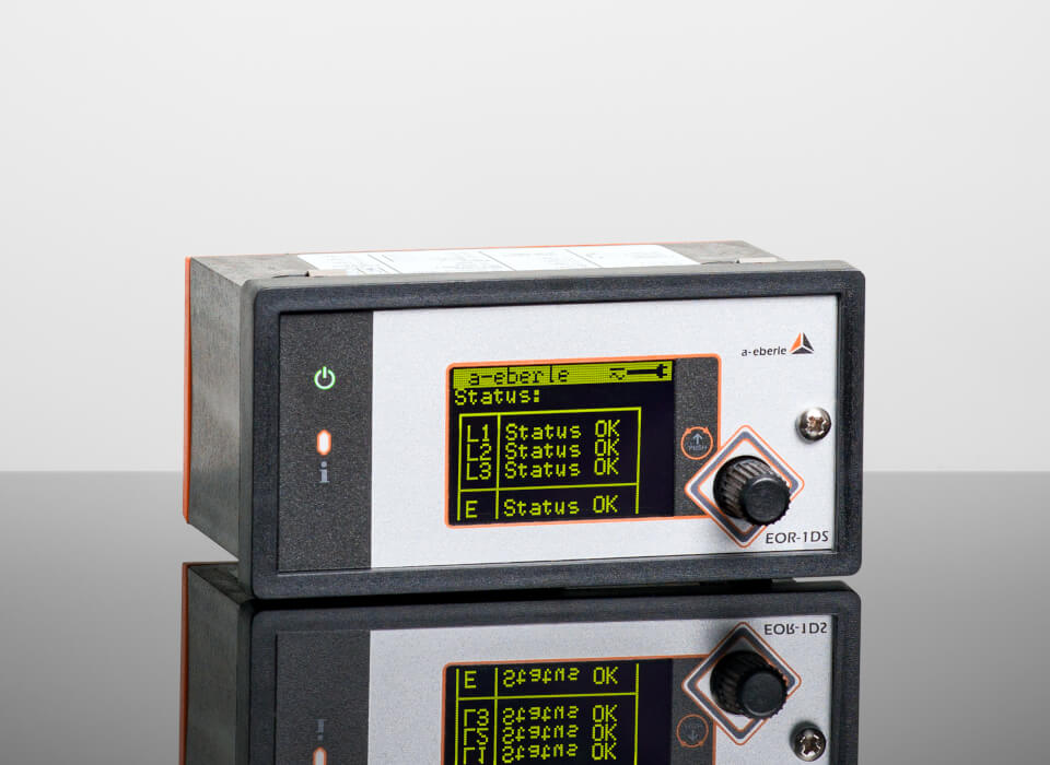
EOR-1DS
Instruction Manual
Installation Manual
Technical Data Sheets
Firmware
Interface Lists
Presentation Flyer: EOR-1DS
Quick Comparison: EOR-1DS vs. EOR-3DS
Cost-Efficient Combined Earth Fault Detection and Short-Circuit Indication for All Grid Types
The EOR-1DS combines short-circuit and earth fault indication in one compact and cost-effective device, providing an economical fault indication solution for grid operators in both compensated and isolated grids. Thanks to intelligent algorithms and a wide range of available location methods, faults are detected accurately, minimising downtimes, reducing operating costs and ensuring security of energy supply.

All Necessary Fault Location MethodsCombined in One Device
With the EOR-1DS, network operators benefit from comprehensive fault location. The device supports a variety of established locating methods that enable reliable and fast identification of faults and which can be combined with each other according to individual customer requirements. Particularly noteworthy is the wattmetric method (cos(φ)), which enables precise detection of earth faults by analysing the active power component of the fault currents. This method is particularly robust against symmetrical grid loads and makes a decisive contribution to reliable fault location in complex grid structures.
Supported Localisation Methods:
- Wattmetric method cos(φ)
- qu2 transient algorithm (transient earth fault method)
- Directional short-circuit and earth fault detection
- Pulse location
- Reactive power direction sin(φ)

Simple Parameterisation via Rotary Switch, SD Card, Modbus or Pre-Parameterised on Delivery
Commissioning the EOR-1DS is particularly user-friendly. All necessary settings can be made directly on the device using a rotary knob - without additional software or external configuration tools. Alternatively, parameterisation is also possible via an SD card or Modbus, or the device is delivered pre-parameterised. This saves time, makes handling easier and reduces potential sources of error, especially during on-site maintenance work.
Large Memory (32 GB)for Fault Records and Logbook
With its 32 GB memory, the EOR-1DS offers extensive capacity for fault records and logbook data. This allows grid operators to carry out long-term analyses and access historical events to better understand sources of faults. The detailed recording and storage of event data provides a sound basis for optimising grid quality, facilitates documentation for regulatory requirements and thus secures the grid supply.
The Grid Status Always in View - Flexible in Your Choice of Sensors
Do you see a risk of grid bottlenecks due to the strong increase in decentralised generators or loads such as electromobility? Then monitor your medium-voltage level closely to keep an eye on trends.
The ‘S’ in the name gives it its meaning: Our EOR-1DS is optimised for the modern and highly accurate small-signal sensors of all major manufacturers on the market (ABB, Zelisko, Greenwood Power, 3M and many more). Of course, there is also the option of current measurement via Rogowski sensors (SR55) and voltage measurement in parallel with a capacitive voltage tester (e.g. Capdis / WEGA). This makes it possible to determine precise current, voltage and power measurement values from the depth of the grid.
Compatible With Classic Transformers as Well
The EOR-1DS can not only measure the voltage in parallel with a capacitive voltage tester (e.g. Capdis or WEGA) or via small signal sensors. It is also possible to connect a classic voltage transformer with 100 VAC / 110 VAC secondary voltage via the U10 adapter.
The same applies to current detection. In addition to the options of using Rogowski sensors (SR55) or the small signal inputs, classic current transformers with 1 A / 5 A secondary current can be connected to the EOR-1DS using the C21/C25 adapters.

Ready for Communication and Interconnection
In addition to connecting the indicator via four freely parameterisable relay contacts and two fixed binary inputs, the EOR-1DS short-circuit and earth fault indicator can also be read out via a Modbus RTU connection over RS485. All information and messages can be queried in the standard register assignment and a large number of the available parameters can be changed.
Short-Circuit and Earth Fault Indicators From A. Eberle
EOR-1DS and EOR-3DS for Future-Proof Local Network Stations
Quick Comparison: EOR-1DS vs. EOR-3DS
Find the Right Short-Circuit and Earth Fault Indicator for Your Application.
EOR-1DS
The Economical Indicator for
the Secondary Substation
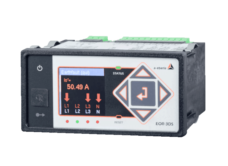
EOR-3DS
The Fault Indicator for
the Digital Secondary Substation
qu2 transient algorithm
Transient earth fault methodDirectional short-circuit and earth fault detection
Pulse location
Wattmetric method cos(φ)
Reactive power direction sin(φ)
❌
❌
Simple operation and parameterisation without software
❌
Extensive cyber security features✔️
Flash memory up to 32 GBCapacitive in parallel with VDS systems, low power sensors (two-wire technology) and classic transducers
Rogowski folding transducers, low power sensors (two-wire technology) and classic transducers
Modbus RTU
❌
❌
❌
❌
qu2 transient algorithm
Transient earth fault methodDirectional short-circuit and earth fault detection
Pulse location
Wattmetric method cos(φ)
Reactive power direction sin(φ)
qui-Method
Restriking faultsHarmonics method
Open setup as required with »AEToolbox« software
Certificate handling, user/role concept and encrypted connections
Extensive cyber security features✔️
Flash memory up to 32 GBCapacitive in parallel with VDS systems, Low power sensors (two-wire technology or RJ45) and classic transducers
Low power sensors (two-wire technology or RJ45) and classic transducers
Modbus RTU/TCP (Incl. "Modbus Master")
IEC 60870-5-101 / 104, IEC 60870-5-103 Including Fault Records, IEC 61850 GOOSE, DNP 3.0
MQTT Management&Operations
MQTT IoT
Patch- and Devicemanagement via MQTT
Mass remote parameterisation and firmware updatesvia MQTT Management&Operations-function
FAQ - Frequently Asked Questions
What is the EOR-1DS earth fault indicator used for?
The EOR-1DS is a combined earth fault indicator and short-circuit indicator for fast fault location. It supports non-directional and directional fault indication and helps narrow down faults within the network.
Which fault location methods does the EOR-1DS support?
The EOR-1DS supports the wattmetric cos(φ) method, the qu2 transient algorithm, directional short-circuit and earth fault detection, pulse location, and reactive power direction sin(φ).
Can the EOR-1DS be parameterized without software?
Yes. The required settings can be made directly on the device using the rotary knob. Parameterization is also possible via SD card or Modbus, and the device can be supplied pre-parameterized.
Which sensors and transformers can be connected to the EOR-1DS?
The EOR-1DS supports small-signal sensors and SR55 Rogowski sensors. Voltage can also be measured in parallel with a capacitive voltage tester. Conventional voltage transformers with 100 VAC or 110 VAC secondary voltage can be connected via the U10 adapter, while 1 A or 5 A current transformers can be connected using the C21/C25 adapters.
How does the EOR-1DS communicate with a control system?
The EOR-1DS supports Modbus RTU communication via RS485. It also provides four freely parameterizable relay contacts and two fixed binary inputs.
Further Earth Fault and Short-Circuit Indicators
Discover Our Range of Products
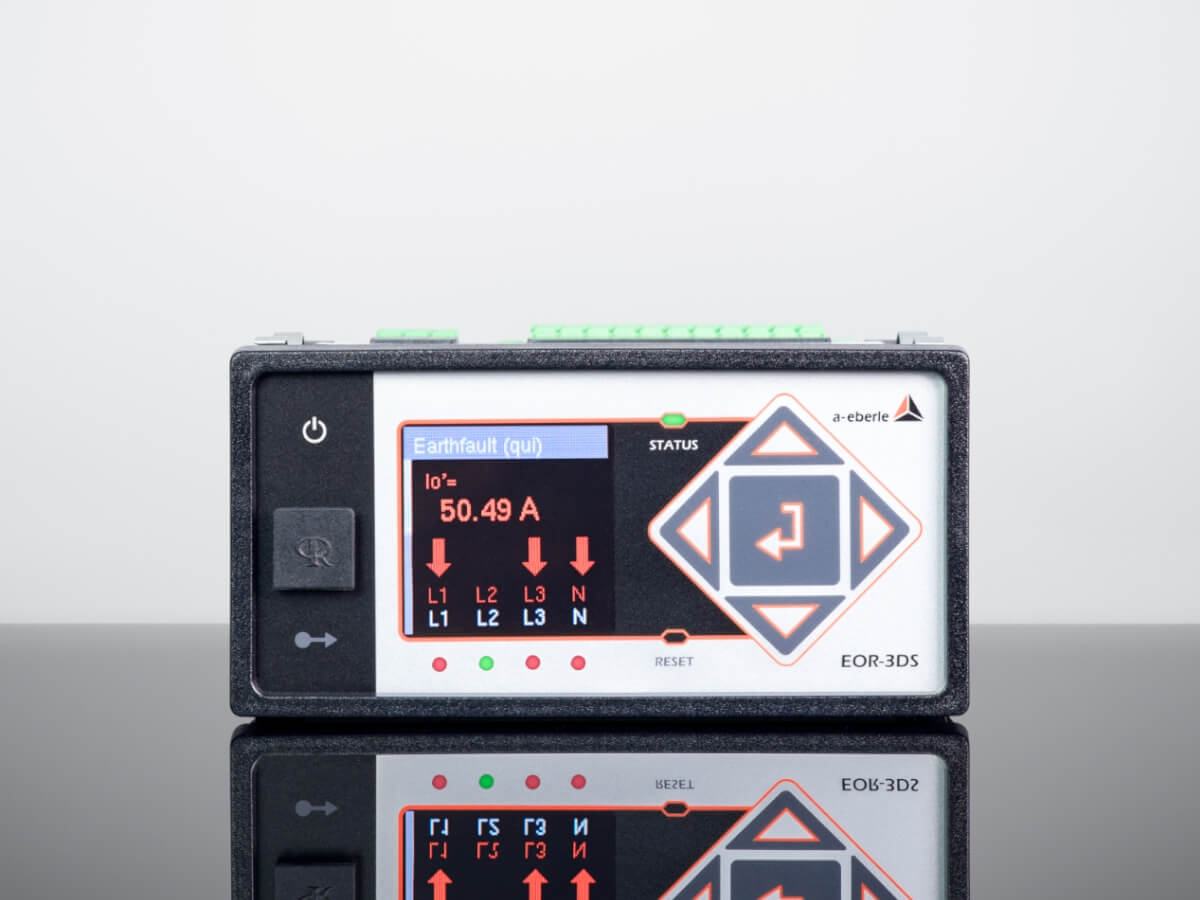
News From the Product Group
EORSys - News

Blogpost
GRUNDIG AKADEMIE visits A. Eberle
7. August 2026
In 2026, the GRUNDIG AKADEMIE Nuremberg visited A. Eberle with a group of trainee technicians. During the visit, the participants gained an insight into our company, technical fields of work and potential[...]
Read more
Webinar
»EORSys« Webinar: Integration of Future-Proof Secondary Substations Into the Distribution Grid - Part 2 | A. Eberle
27. July 2026
Webinar recording from 2026-07-15: »EORSys« -Integration of Future-Proof Secondary Substations Into the Distribution Grid with EOR-1DS & EOR-3DS - Part 2[...]
Read more
Blogpost
A. Eberle named one of the TOP 100 Innovators for 2026
22. July 2026
As part of the 2026 TOP 100 Awards, we had the honour of receiving a special accolade in Heidelberg last week – presented in person by Christian Wulff, former Federal President and mentor of the TOP[...]
Read more
General Knowledge
Digital Substation
17. June 2026
A digital secondary substation combines measurement, fault location and secure data analysis to improve transparency across medium- and low-voltage distribution grids.[...]
Read more
Blogpost
International Partner Week 2026 - Exchange, knowledge transfer and collaboration in Nuremberg
1. June 2026
We were delighted to welcome our international partners to Partner Week 2026. The chance to chat in person, seeing familiar faces and making new acquaintances made the week a special one for us.[...]
Read more
Blogpost
A. Eberle and Bregal Unternehmerkapital enter into a growth partnership
14. April 2026
A. Eberle and Bregal enter into a growth partnership. The partnership with BU is intended to accelerate A. Eberle’s international expansion, innovation and technological advancement.[...]
Read more
Webinar
»Cyber Security« Webinar: A Challenge for European Energy Companies
3. December 2025
Webinar recording from 2025-11-26: »Cyber Security« - A Challenge for European Energy Companies[...]
Read more
Blogpost
A. Eberle at the Schwabach City Run 2025
24. November 2025
A. Eberle was represented by 37 participants at the 2025 Schwabach City Run, setting a new internal record for participation. Particularly noteworthy is Benjamin Rentsch's first place in the M 35 40 age[...]
Read more
Webinar
»EORSys« Webinar: Integration of Future-Proof Secondary Substations Into the Distribution Grid - Part 1 | A. Eberle
15. October 2025
Webinar recording from 2025-10-15: »EORSys« -Integration of Future-Proof Secondary Substations Into the Distribution Grid with EOR-1DS & EOR-3DS - Part 1[...]
Read more
General Knowledge
Power in Multiphase Systems
7. August 2025
This technical report highlights the special features of power transmission in three-phase systems and offers valuable insights into the optimisation and analysis of modern power grids.[...]
Read more
Webinar
»EORSys« Webinar: EOR-1DS - the Economical Fault Indicator for the Secondary Substation
22. July 2025
Webinar recording from 2025-07-16: »EORSys - EOR-1DS - the Economical Fault Indicator for the Secondary Substation«. [...]
Read more
Blogpost
Visit From the Rudolf Diesel Technical School at A. Eberle
15. July 2025
We were happy to welcome you, Rudolf-Diesel-Fachschule! Yesterday, we had the pleasure of welcoming two classes of future electrical engineering technicians from the Rudolf-Diesel-Fachschule Nürnberg[...]
Read more
Blogpost
TOP 100 Awards 2025: Innovation for the Energy Future
15. July 2025
💡 As part of the TOP 100 Awards 2025, we were honored to receive a special recognition last week in Mainz – personally presented by TV host and science journalist Ranga Yogeshwar.[...]
Read more
Blogpost
University Excursion: Pentecost Excursion of the Friedrich-Alexander-University Erlangen-Nuremberg (FAU)
14. July 2025
As a company dedicated to innovation, education, and the energy transition, we are pleased to have once again supported the Whitsun excursion of Friedrich-Alexander University Erlangen-Nuremberg (FAU)[...]
Read more
Blogpost
Further Growth at A. Eberle
14. July 2025
Welcome to the team! We welcome our new colleagues at A. Eberle.[...]
Read more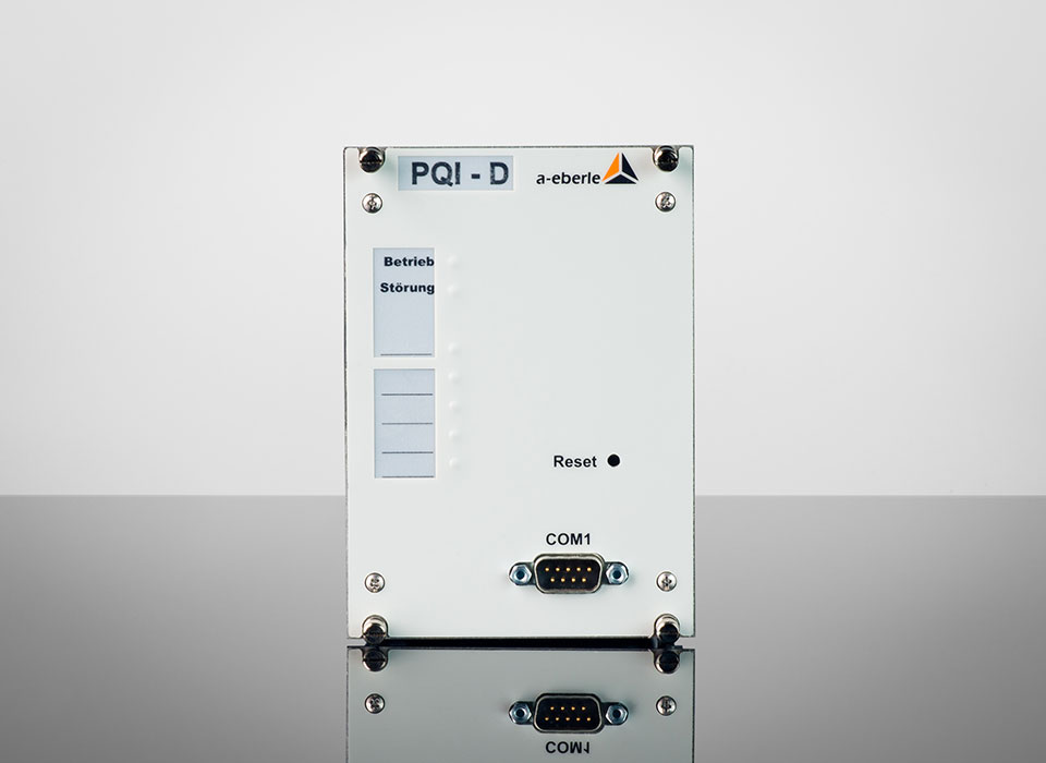
Product innovation
Product Discontinuation: Power Quality Interface (PQI-D) as of 31.12.2026
27. March 2025
The Power Quality Interface (PQI-D) product can only be ordered up to and including 31 December 2026.[...]
Read more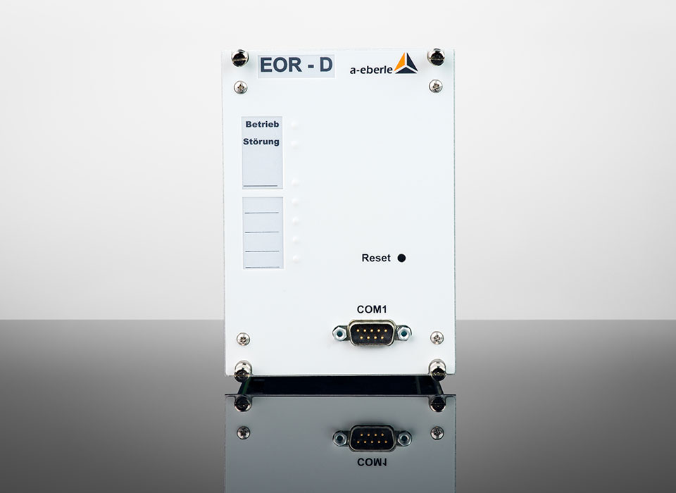
Product innovation
Product Discontinuation: Earth Fault Locating Relay (EOR-D) as of 31.12.2026
27. March 2025
The product earth fault locating relay for multiple outgoing circuits (EOR-D) can only be ordered up to and including December 31st, 2026.[...]
Read more
Webinar
»EORSys« Webinar: Digital Secondary Substations in the Distribution Grid of the Future
16. September 2024
Webinar recording from 2024-05-07: »EORSys - Digital Secondary Substations in the Distribution Grid of the Future«. [...]
Read more
Blogpost
International Partner Week 2024 - a Look Back
29. August 2024
Our International Partner Week 2024 - many old friends and new faces were our guests, it was a pleasure.[...]
Read more
Webinar
»EORSys« Webinar: Future-Proof Integration of Digital Substations in the Distribution Grid
15. July 2024
Webinar recording from 2024-07-11: »EORSys - Future-proof Integration of Digital Substations in the Distribution Grid«. [...]
Read more