Conductors as capacitors
In the conductors of electrical power supplies, a distinction is made between the operating capacitance Cb, the three phase-phase capacitances CL and the three phase-earth capacitances Ce. The operating capacitance is determined by the capacitive reactive power demand of a conductor and the phase-earth capacitance of the single-phase fault current in the insulated or compensated networks. Single conductor cables are designed to have no phase-phase capacitance.
The capacitance of a parallel plate capacitor depends on the size of the plates, the electrical properties of the dielectric and the distance between the plates.
C= \frac{A * ε}{a}A = Plate size
ε = Dielectric constand
a = Distant between plates
An electrical conductor is a cylindrical capacitance where the surface is a circle. And thus the equation changes.
C= \frac{2*\pi *l * ε}{ln\frac{a}{r}}l = Length of the cylinder
ln = Natural logarithm
a = Radius of the insulation
r = Conductor radius
Single core radial field cable
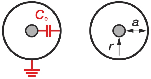
C_{b}=C{e}C= \frac{2*\pi *l * ε_{0}*ε_{r}}{ln\frac{a}{r}}Cb = Operating capacitance
Ce = Phase-earth capacitance
e0 = Electrical field constant 8.85 pF/m
er = Relative dielectric constant
a = Radius of the insulation
r = Radius of the conductor
Three-core belted cables
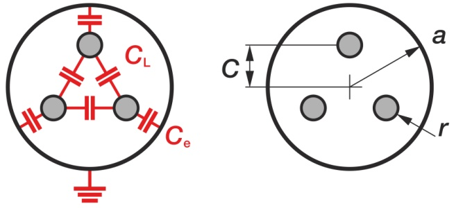
C_{b}=C_{e}+3*C_{L}C= \frac{2*\pi *l * ε_{0}*ε_{r}}{ln\frac{a^{6}-c^{6}}{3*c^{2}*r*a^{3}}}


