Transformer for alternating values
The direct connection of measuring devices into the network is limited for safety reasons to values below approximately 500 V to 800 V for voltages and 10 A for currents. Inputs with higher operating values are adapted to the input range of the measuring equipment with transformers.
Transformers for alternating values are low-power transformers operating well below the saturation limit of the iron core. The high values of a grid value (primary values X1) are accurately amplitude and phase mapped to lower values (secondary values X2) by conversion and galvanic separation. The grid values can therefore be measured more easily and with less danger.
Nominal translation
The nominal values X1n, the primary values and X2n the secondary values and thus the nominal translation Kn determine the choice of the transformer.
K_{n} = \frac{X_{1n}}{X_{2n}}K_{nu} = Voltage\:transformer\:nominal\:translationK_{ni} = Current\:transformer\:nominal\:translationExample 1.1
Current transformer data:
X_{1n} = 1000 A; X_{2n}= 5 ANominal translation of the current transformer:
K_{ni} = 1000 A : 5 A = 200Conversion of measured values of the power
The measured value of the power on the line side is the product of the measured value of the power in the secondary circuit and the nominal translation of the current and voltage transformers.
P_{prim} = P_{sek} * K_{nu} * K_{ni}This correlation is the same for all types of network. In three-phase networks, the nominal translation of all voltage transformers and current transformers must be the same.
Example 1.2
Network data: 300 MW, 110 kV
Measurement transformer:
K_{nu} = 110 kV / \sqrt{3} : (100 V / \sqrt{3} )= 1,1 *10^{3}K_{ni} = 1200A /1A =1,2 *10^{3}Power value on the secondary side:
P_{Sek}= (300*10^{6}W):(1,0*10^{3}*1,2*10^{3}) = 300 : 1,2 \newline= 250 WCurrent transformer
A current transformer is a transformer that is whose secondary winding is almost short circuited. The secondary circuit must always be closed. Operation with an open current circuit (no load, open secondary winding), because of the non-existing mutual induction and the consequent multiplication of the iron losses, causes major heating of the transformer core, and in extreme cases, an explosion. Because of the large ratio of the primary to the secondary winding, in this case a high, dangerous voltage can result at the terminals of the secondary winding, which can also cause arcing between the windings. For these reasons, fuses must not be used in the secondary circuit.
Earthing of the secondary winding
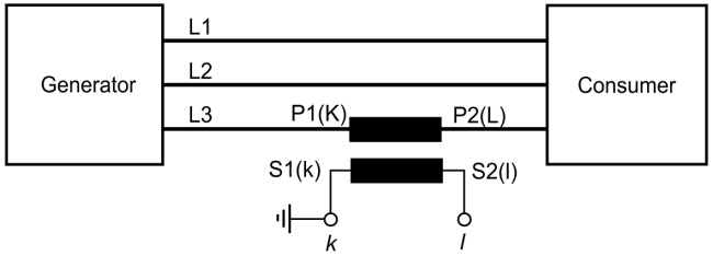
For safety reasons, the secondary winding of a current transformer that is installed in a high-voltage grid is grounded on one side to prevent the endangerment of the operating personnel due to high voltage on a breakdown of the winding insulation. This requirement is defined in VDE 0100 for measurement transformers from series 3 (operating voltage 3 kV) upwards.
Earthing of the secondary winding is not required for the series 0.5 and 1. Often, however, this is necessary for technical reasons, in order to create a defined reference point in a current circuit and dissipate interference voltages to earth.
Nominal value I2n
The standardised nominal values of the secondary currents are:
1 A, 2 A and 5 A.
Accuracy classes of current transformers
Current transformers are produced in the classes 0.1; 0.2; 0.5; 1; 3; 5.
Current transformer terminal designations
In accordance with DIN 0414, the terminal designations for the primary winding are K and L and k and l for the secondary winding.
K on the generator side, and L on the consumer side.
