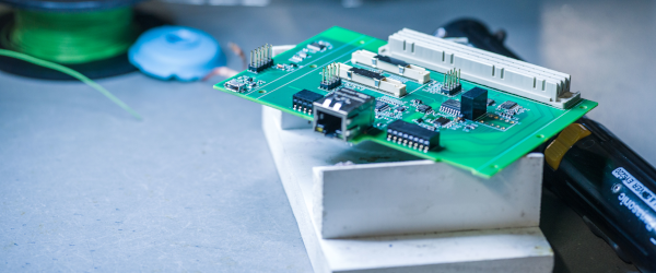
Voltage Regulation With Step Transformers in Parallel to Busbars (Part 3)

Info Letter No. 11

Measurement of the Circulating Current

Direct measurement of the circulating current is not possible with the usual measurement equipment. The calculation of the circulating current from the difference between the off-load voltages and the short-circuit impedance of the windings involves a relatively high cost, because the exact actual values of the complex quantities are required for this. For a voltage control based on the principle of circulating current minimization, proxy values for the circulating current can therefore be used. These proxy values are not universal, but nearly proportional for the circumscribed practical realities of the circulating current and sufficiently accurate for the stepped voltage regulation.

Calculation of the Circulating Current

The magnitude and the angle of the circulating current can be calculated using the generally available complex measurement values, the transformer currents ITA and ITB.

\underline{I}_{cir}=\underline{I}_{TA}-(\underline{I}_{TA}+\underline{I}_{TB})( \frac{\underline{Z}_{kB}}{\underline{Z}_{kA}+\underline{Z}_{kB}})

With this equation the circulating current can also be correctly determined with SrASrB ; ukrAukrB ; jkrAjkrB. The load data (load factor, load type, power factor) have no effect on the result.

Determination of the Circulating Current Using the ∆Sinφ Procedure

In parallel operation on a busbar for SrA = SrB and ukrA = ukrB and
φkrA = φkrB = 90°, the circular current is given by the measured reactive currents IqA = ITA sinφTA and IqB = ITB sinφjTB of transformers A and B. If these conditions are met, then it is permissible to calculate the values with only the complex values.

Automatic Voltage Regulation With REGSys® – Proven a Thousand Times Over, Multifunctional and Flexible

Need More Information?

Contact Us!


Contact

Info-Letters

Click Through Our Info Letter Series

News From the Product Group

REGSys® - News

Training Video

»REGSys®« Training Video 8: Overview SCL-Config for IEC 61850

In this video you will learn how you can export a CID file, how to adjust the IED name and working with the SCL-Config.

Read more

Training Video

»REGSys®« Training Video 7: How to Use the Winconfig Software

In this video you will learn how to create a new parameter file, how to upload setting files or download setting files from the Scada card and what kind of parameters a setting file contains.

Read more

Training Video

»REGSys®« Training Video 6: Firmware Update via Winconfig

In this video you will learn when it is reasonable to use the WinConfig for a firmware update and how to do a firmware update with the WinConfig.

Read more

Training Video

»REGSys®« Training Video 5: Firmware Update via RPL2

In this video you will learn how to create a physical connection before the firmware update, how to use the RPL2 software and how to do a small test after the firmware update.

Read more

Training Video

»REGSys®« Training Video 4: Changing the Default Password

In this video you will learn how to connect the SCADA card to your computer, start the software WinConfig and change the default password and define a new one.

Read more

Training Video

»REGSys®« Training Video 3: Changing IP Address via Winconfig

In this video you will learn how to define a new IP address, how to interpret the “States of detected boards” and how to determine the port numbers of the physical ports.

Read more

Training Video

»REGSys®« Training Video 2: Changing IP-Address via Webserver

In this video you will learn how to access the web server, how to change the network settings in the web server.

Read more

Training Video

»REGSys®« Training Video 1: Adjusting the Time Synchronisation

In this video you will learn how to connect the SCADA card to your computer, start the software WinConfig and change the default password and define a new one.

Read more

General Knowledge

Measuring the voltage drop

The voltage drop is the difference between the voltage at the beginning and end of an electrical line. In an electrical network, the voltage can be reduced by the resistance and impedance of the lines, resulting in a lower voltage reaching the consumer than was originally fed in. Find out everything about measurement and calculation in this article!

Read more

Blogpost

International Partner Week 2024 – a Look Back

Our International Partner Week 2024 - many old friends and new faces were our guests, it was a pleasure.

Read more

General Knowledge

REGSys® Parallel Regulation of Transformers With Tap-Changers

The regulation of transformers with tap changers is an essential subject within the field of power supply and distribution. Today these tasks are accomplished electronically with high regulation quality. Digital regulators, such as the freely programmable REGSys® voltage regulator system, are in use.

Read more

Info letter

Info Letter No. 16: Hot-Spot Temperature and Service Life of Transformers

The failure of a transformer not only has major economic consequences for the energy supplier, it can...

Read more

Info letter

Info Letter No. 13: Parallel Operation of Step Transformers

The rule of thumb that with parallel operation of transformers the ratio of the rated outputs should not...

Read more

Info letter

Info Letter No. 10: Voltage Regulation With Step Transformers Parallel to Busbars (Part 2)

The following considerations apply to a symmetrical operation of a three-phase network, so that the...

Read more

Info letter

Info Letter No. 9: Voltage Regulation With Step Transformers in Parallel to Busbars (Part 1)

Within a station, the transformers are in close proximity. Therefore, the line impedances between the...

Read more

Info letter

Info Letter No. 7: Load-Dependent Voltage Change

For the regulation of the voltage ULoad at a predetermined value at the specified load point (e.g. the...

Read more

Info letter

Info Letter No. 4: Summation of Alternating Currents

For the parallel connection of power sources, the principle of superposition applies, when all resources...

Read more

Special Publication

Regulating the Active and Reactive Power With REGSys®

he voltage regulator REG-D(A) is normally tasked with controlling voltage on the secondary side of a transformer. The main task here is to achieve the best possible balance between voltage stability and the number of taps...

Read more

Special Publication

The REGSys® Triple-Wound Feature

Since then, it has become possible to use the feature for other application such as so-called “energetic recovery” or to implement applications requiring a second voltage (U1, U2) and current (I1, I2) measurement. In these...

Read more

Special Publication

Safely Regulate the Load Flow

Phase-shifting transformers or shunt regulators are special power transformers. They allow the active power flow (load flow) in alternating current networks to be controlled. During tapping, the ...

Read more

Contact request:


* Mandatory

Your data is being processed

a-eberle kontakt newsletter ×

Our seminars &
webinars

► Register here!

x