+++ PQ-Box Trade-in Promotion: Only From 01.09. – 31.12.2024 +++ Attractive Discount on Your PQ-Box Order +++ Click Here for More Information! +++

+++ PQ-Box Trade-in Promotion: Only From 01.09. – 31.12.2024 +++ Attractive Discount on Your PQ-Box Order +++ Click Here for More Information! +++

+++ PQ-Box Trade-in Promotion: Only From 01.09. – 31.12.2024 +++ Attractive Discount on Your PQ-Box Order +++ Click Here for More Information! +++

Load-dependent voltage change

Info Letter No. 7

Regulation on the voltage

For the regulation of the voltage ULoad at a predetermined value at the specified load point (e.g. the end of a branch conductor), the load-dependent difference between the voltage at the step transformer and the voltage at the load point can be compensated by a corresponding automatic adjustment of the setpoint of the voltage regulator in order to keep the voltage at the load point constant regardless of load fluctuations.

U_{sett2} = U_{sett1} + U_{comp}

Ukomp : Difference between the effective values of UT and ULoad

Voltage drop on a three-phase conductor

For high-voltage power lines, in the energy technology for determining the voltage difference between the beginning and end of a line, instead of the general line equations simple approximate formulas are used, where the equivalent circuit on which it is based is shown in Figure 1. The results meet the accuracy requirements of the voltage regulation, which can only be carried out in stages.

The simplification of the general conduction equation is possible with power lines because their lengths always “short compared to the wavelength l” of the fundamental of the operating voltage (l approximately 6,000 km at 50 Hz). As limits for the following approximate formulas, line lengths of about 150 km for overhead lines and 50 km for cables apply.
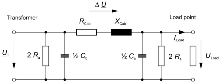
Equivalent circuit of the short electricity lines

For the load-dependent voltage difference (phase-neutral voltage) on the three-phase line between the tapped transformer and the load point the following applies:

\Delta{U}=U_{T}- U_{Load} = Z_{Cab}*I_{Load}= \Delta{U}e^{j(φZ_{Cab}+φI_{Load})}

ILoad        of the current consumed in the consumer circuit at the load point
φCab        angle of the conductor impedance ZCab
ILoad        angle of the current ILoad at the load point
               (φILoad = φULoad – φZLoad)
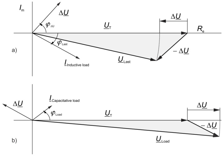
Voltage Vector of the single-phase equivalent circuit in a short electicity line

a) With an inductive load the voltage drop in the line is positive and thus the voltage ULoad at the load point is less than the voltage UT at the transformer.

b) With a capacitive load the reverse applies, i.e. the voltage at the load point is higher than at the transformer. Such loads mainly occur at night.

Line simulation

Because the actual value of the voltage on the load on the voltage regulator normally is not available, the voltage drop on the line is approximated in a line simulation of RCab and XCab, through which the current I = ILoad (w2 / w1) flows. The discharge resistance and the operating capacitance of the equivalent circuit is not taken into account and the small difference between the angles at the beginning and end of the line (transformer and load point) is also neglected.

Load-dependent voltage drop

In the series control, for the change in the set point, only the difference of the effective values of transformer voltage and load voltage is a determinant, so that the angles of the two voltages are meaningless in this context. The complex voltage difference ∆U determined from the line simulation (the impedance of the line) is not different from the difference of the two effective values, so that the complex voltage difference cannot be used directly to change the setpoint.

Need more information?

Contact us!


Contact

News From the Product Group

REGSys® - News

Blogpost

International Partner Week 2024 – A look back

Our International Partner Week 2024 - many old friends and new faces were our guests, it was a pleasure.

Read more

General Knowledge

REGSys® Parallel Regulation of Transformers with Tap-Changers

The regulation of transformers with tap changers is an essential subject within the field of power supply and distribution. Today these tasks are accomplished electronically with high regulation quality. Digital regulators, such as the freely programmable REGSys® voltage regulator system, are in use.

Read more

Info letter

Info Letter No. 16: Hot-spot temperature and service life of transformers

The failure of a transformer not only has major economic consequences for the energy supplier, it can...

Read more

Info letter

Info Letter No. 13: Parallel operation of step transformers

The rule of thumb that with parallel operation of transformers the ratio of the rated outputs should not...

Read more

Info letter

Info Letter No. 11: Voltage regulation with step transformers in parallel to busbars (Part 3)

Direct measurement of the circulating current is not possible with the usual measurement...

Read more

Info letter

Info Letter No. 10: Voltage regulation with step transformers parallel to busbars (Part 2)

The following considerations apply to a symmetrical operation of a three-phase network, so that the...

Read more

Info letter

Info Letter No. 9: Voltage regulation with step transformers in parallel to busbars (Part 1)

Within a station, the transformers are in close proximity. Therefore, the line impedances between the...

Read more

Info letter

Info Letter No. 4: Summation of Alternating Currents

For the parallel connection of power sources, the principle of superposition applies, when all resources...

Read more

Special Publication

Regulating the Active and Reactive Power with REGSys®

he voltage regulator REG-D(A) is normally tasked with controlling voltage on the secondary side of a transformer. The main task here is to achieve the best possible balance between voltage stability and the number of taps...

Read more

Special Publication

The REGSys® Triple-Wound Feature

Since then, it has become possible to use the feature for other application such as so-called “energetic recovery” or to implement applications requiring a second voltage (U1, U2) and current (I1, I2) measurement. In these...

Read more

Special Publication

Safely Regulate the Load Flow

Phase-shifting transformers or shunt regulators are special power transformers. They allow the active power flow (load flow) in alternating current networks to be controlled. During tapping, the ...

Read more

Contact request:


* Mandatory

Your data is being processed

a-eberle kontakt newsletter ×

Our seminars &
webinars

► Register here!

x