What is an earth fault?
Definition
An earth fault is an unintended electrically conductive connection between an electrical conductor and earth or earthed parts. If this fault occurs in a network with a rigidly earthed neutral point, it is also referred to as an earth fault with an earth short circuit, which usually results in the network being switched off immediately.
In networks with an isolated neutral point and in compensated networks, there is no short-circuit current; the fault current is determined by the conductor-to-earth capacitance of the network and, in the compensated network, by the degree of compensation. In the event of an earth fault in medium-voltage systems or high-voltage systems with earth fault compensation, the system can continue to be operated.
Systems with an isolated neutral point can only continue to operate in rare cases with a small system size (small capacitive earth fault current) in the event of a fault. If earth faults occur simultaneously at several points in the system, a double earth fault or multiple earth fault occurs, which can lead to high short-circuit currents even in isolated and compensated systems.
What happens during an earth fault?
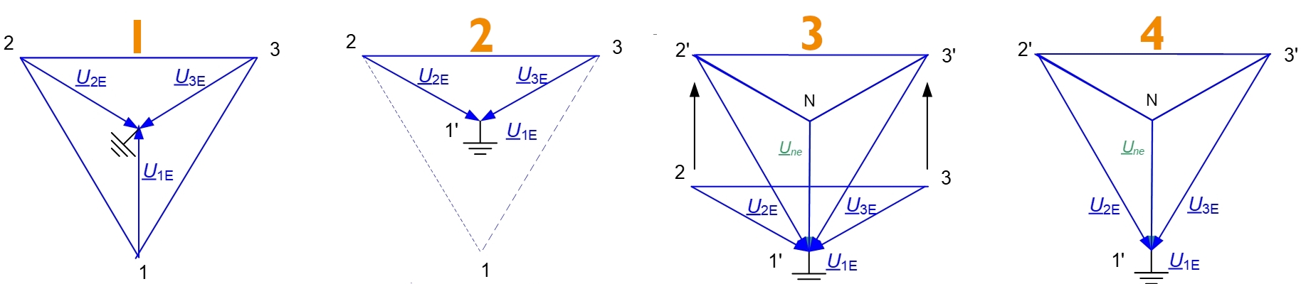
The behavior of the phase-to-earth voltages in the event of an earth fault in the isolated and compensated system is shown below:
- Symmetrical voltage triangle in a healthy network
- Discharge process of the faulty phase: The phase-to-earth voltage of the affected phase (here U1E) conductor collapses; in the case of a full earth fault, U1E goes to zero
- Charging process of the healthy phases: The phase-to-earth voltages of the healthy phases increase by the factor √3 to the value of the interlinked voltages, the zero sequence voltage UNE (vectorial sum of the three L-E voltages Une = UL1+UL2+UL2) increases from the operating value (in the “ideal network” 0 V, in reality a few volts) to a higher value (corresponds at most to the value of the phase-to-earth voltage in the case of a saturated earth fault)
- Stationary earth fault state (only for continuous earth faults): The phase-to-earth capacitances CLE of the two fault-free conductors are continuously recharged. The voltages of the healthy phases remain at the increased value (at the saturated earth fault value of the interlinked voltages) as long as the earth fault persists. The zero sequence voltage also retains its increased value.
Charging and discharging process with earth fault
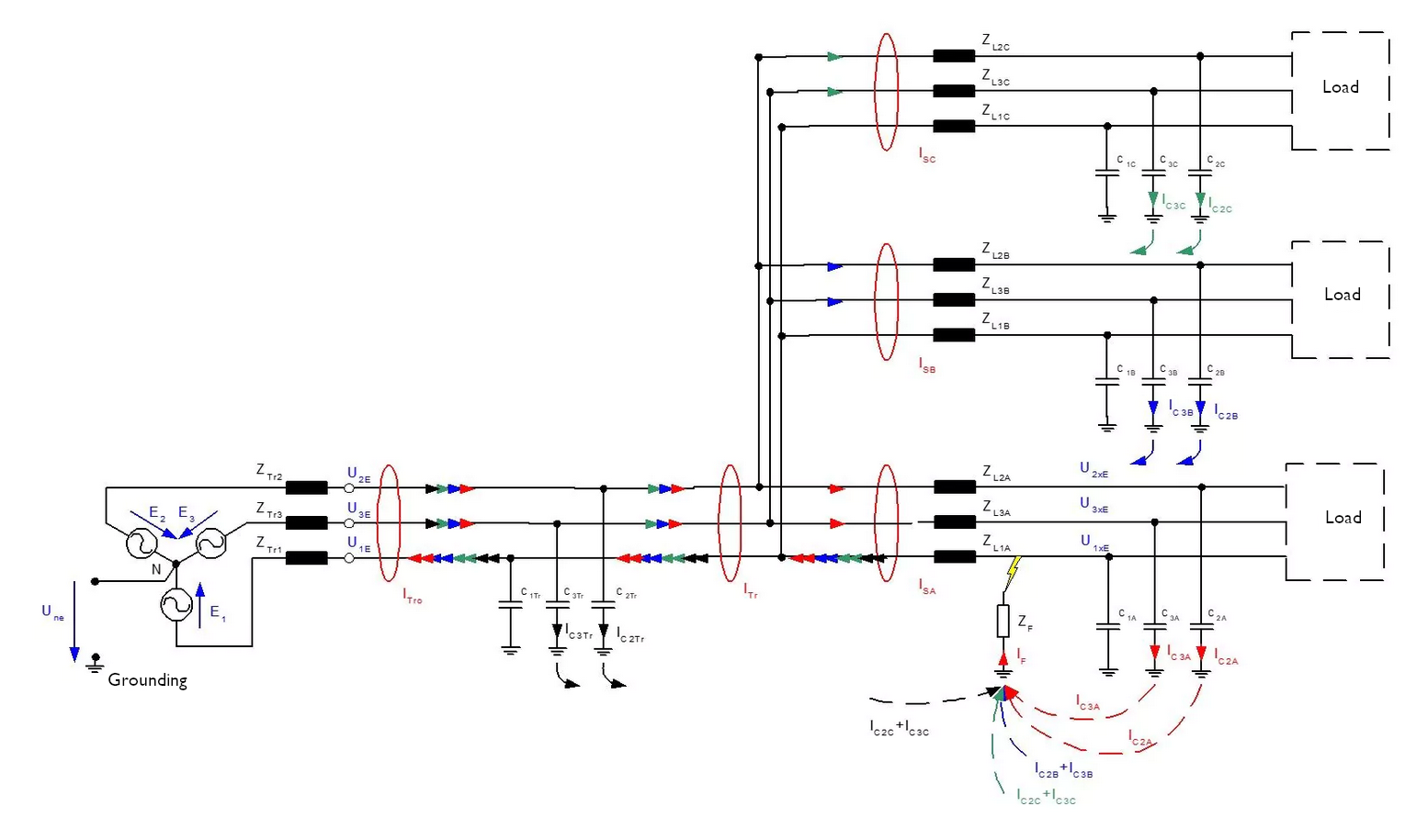
The charging and discharging processes are short-term transient processes. After the end of this high-frequency transient process, which is often referred to as an earth fault wiper, the capacitive earth fault current ICE flows at the fault location in the case of a stationary earth fault in the isolated system, which is made up of the sum of all conductor-to-earth capacitances of the system and thus correlates with the size of the system, among other things. Regardless of the fault location, IF = ICE applies to the fault current in the isolated system in the event of a saturated earth fault. The current flows in the isolated system are explained using the following example.
Causes and examples of earth faults
An earth fault can have many causes
- sagging high-voltage lines when the line touches the ground surface or objects on the ground.
- aged or damaged insulation
- Dirty insulators
- Foreign objects such as trees, branches or birds on overhead lines
How does an earth fault occur / Examples of earth faults
- Overvoltages in a power grid can damage the insulation and cause an earth fault
- Stationary material fatigue or wear, which causes the insulation to be damaged. If the insulation (dielectric) in cables is damaged, re-ignition faults also frequently occur
- short earth fault wipers on overhead lines, e.g. through contact with trees
- Contact with earth on overhead lines
In which situations/at which locations do earth faults occur particularly frequently?
- Construction sites: On construction sites, there is often an increased likelihood of mechanical damage to cables and wires, which can lead to earth faults.
- Old or neglected infrastructure: In outdated or poorly maintained electrical installations and supply networks, there is an increased risk of insulation failure and other problems that can lead to earth faults.
- Areas with downed power lines: Contact between a high-voltage line and the ground surface or objects on the ground results in an earth fault.
- Underground cabling: In situations where electrical cables are buried underground, there is an increased risk of earth faults due to ground movement, corrosion and moisture.
- Residential areas: Ground faults can occur in residential areas, especially if the electrical infrastructure is outdated or there are problems with the wiring. High and medium voltage lines in residential areas can also cause earth faults if they are damaged or sag.
- Industrial facilities: In industrial environments, such as factories and production facilities, there is an increased risk of earth faults due to the complex electrical systems and the high electrical load.
Consequences and problems of earth faults
The following problems or dangers exist with earth faults
- If the network does not have earth fault compensation, high electrical currents flow in the ground at the point of the earth fault, which can cause high step voltages and touch voltages that are life-threatening for people and animals. If the permissible step and touch voltages are not complied with in the event of an earth fault (in a rigidly earthed system and usually also in an insulated system), the system must be switched off immediately.
- The earth fault can cause sparks and arcs and thus fires.
- Grids without earth fault compensation must be switched off in the event of an earth fault and a power failure occurs
- In an insulated and compensated system, the voltages of the healthy conductors increase in the event of an earth fault, which places additional stress on the insulation. Extra-high-voltage grids are therefore operated with rigid earthing, as the additional insulation effort would not be economical.
Earth fault clearing/compensation
Petersen coils are used in medium and high-voltage networks so that in the event of a single-pole earth fault, the capacitive current across the fault location is compensated by an inductive current of approximately the same magnitude but in the opposite direction. For this purpose, the coil must be set to an inductive resistance XL in the healthy state of the network, which corresponds approximately to the capacitive resistance XC of the network.
Earth fault compensation in the three-phase system is shown in the following example analogous to the example for the isolated system. With full compensation by the compensation coil, the capacitive earth fault current Ice is fully compensated and in the event of an earth fault, the current at the fault location becomes IF=0.
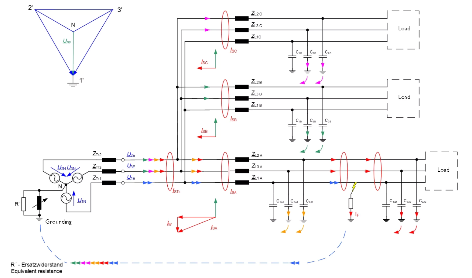
Real grids are generally not fully compensated, but usually operated slightly overcompensated, as the zero sequence voltage is highest at full compensation (at the resonance point) and therefore one of the conductor voltages also assumes the most excessive value.
The degree of over- or under-compensation is indicated by the so-called detuning factor v.
v = (IL – IC) / IL
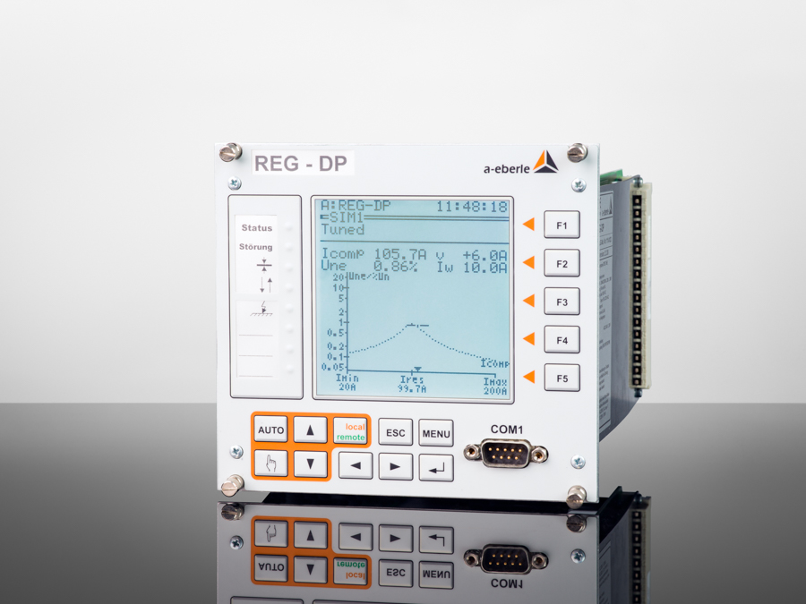
The resonance point and therefore the ideal tuning point for the earth fault suppression coil changes in real networks, as the network capacitance changes due to switching. Automatic control of the coil is important to ensure that it is always tuned as appropriately as possible for the current grid status. This can be done with the REG-DP arc suppression coil regulator from A. Eberle. The REG-DP calculates the correct earth fault compensation automatically and continuously by measuring the resonance curve.
Earth fault location
Although continued operation of the grid is possible in compensated phases, the earth fault still places an additional load on the grid by increasing the voltages of the healthy phases. Fast and reliable earth fault detection and localization is therefore necessary.
A variety of locating algorithms are available to detect the earth fault and localize the earth fault, depending on the respective framework conditions
In order to make optimum use of the advantages of the individual earth fault location methods in different earth fault situations, network types and measurement conditions, a large number of methods are implemented in the earth fault indicators and earth fault location devices from A. Eberle:
- Wiper method (qu2 method)
- Qui method for intermittent faults / re-ignition qui
- Reactive current method / sin(phi) method
- Wattmetric method / cos(phi) method (with or without residual wattage current increase)
- Harmonic method
- Pulse detection
Differentiation of our locating devices according to locating method
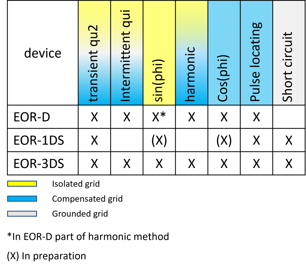
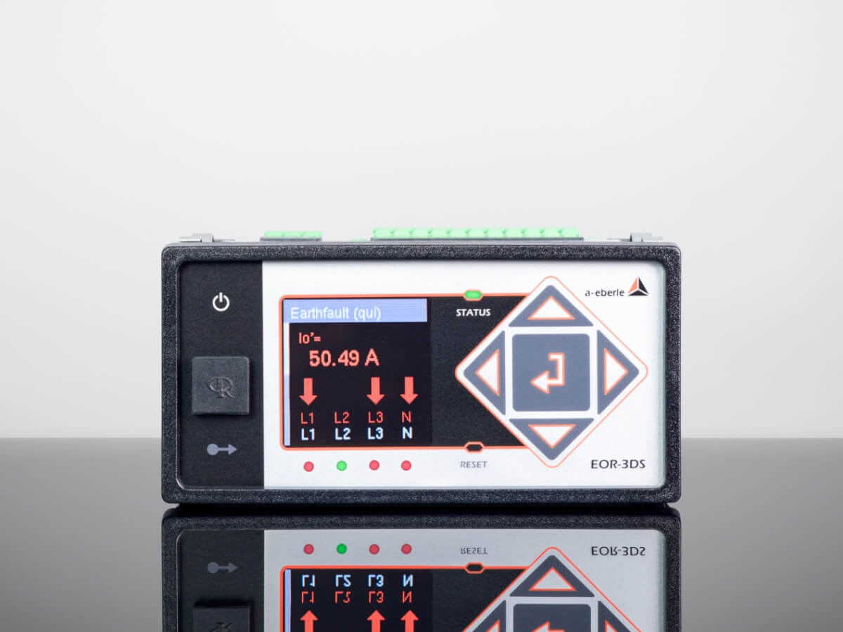
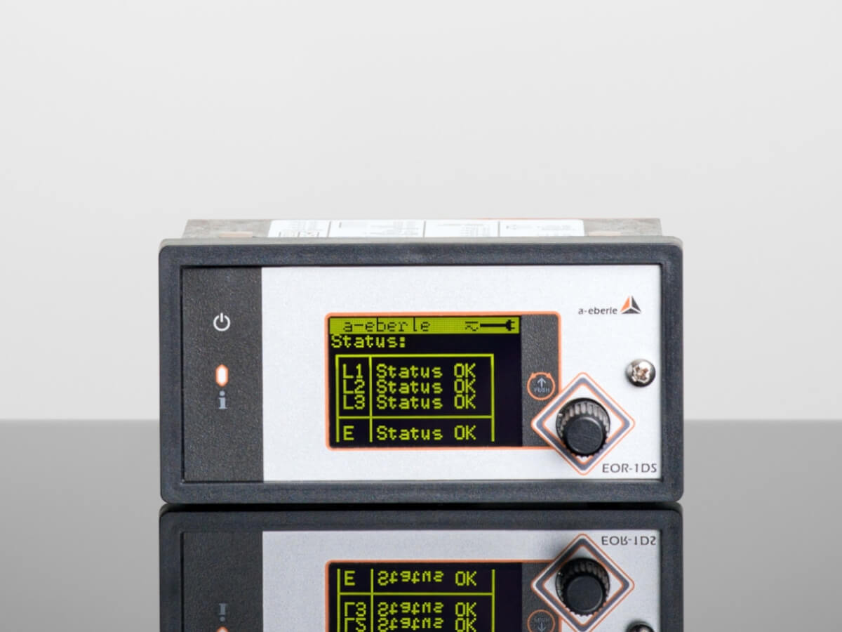
The following table shows an overview of the fault locating devices from A. Eberle and the methods implemented in each case for earth fault location. The combined short-circuit and earth fault indicators EOR-3DS and EOR-1DS have a short-circuit detection function for displaying and reporting short-circuits in addition to the earth fault location functions.
Another important feature of A. Eberle’s locating devices is their high degree of flexibility and adaptability to different areas of application. The devices are designed to be used in various industrial environments, whether in power generation, distribution or industrial automation. In addition, they offer advanced diagnostic capabilities that enable precise monitoring and analysis of electrical networks. This versatility makes A. Eberle’s products a preferred choice for companies looking for reliable and powerful location solutions for their electrical installations.
Differentiation of our locating devices according to main characteristics
The main characteristics of the different fault locating devices from A. Eberle are clearly presented here:
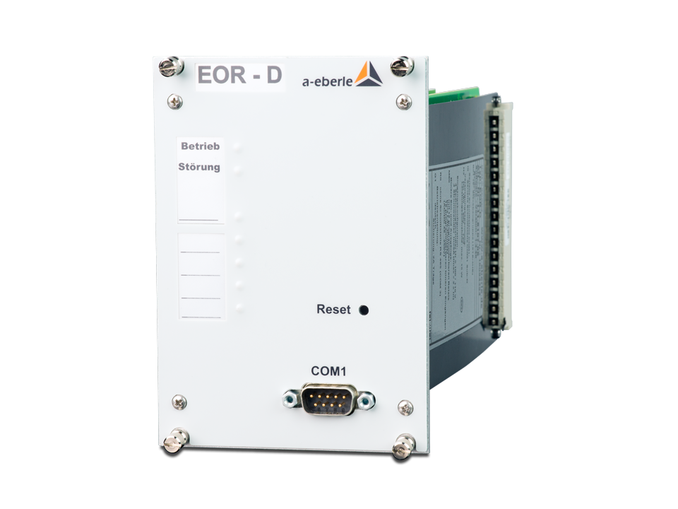
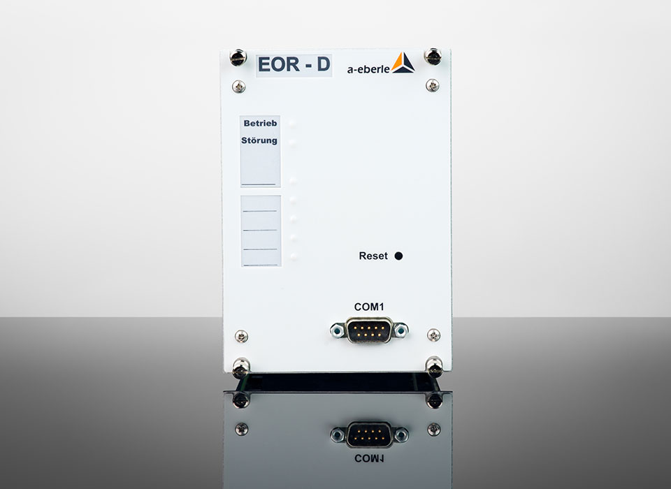
EOR-D
- Extensive locating functionality
- Monitoring of up to 4 outlets with one device (up to 16 outlets per subrack)
- Can be combined with other A. Eberle devices in 19″ subracks:
- REG-D – voltage regulator for tapped transformers
- REG-DP – freely programmable regulator for Petersen coils
- PQI-D – Power Quality Interface for low, medium and high voltage networks
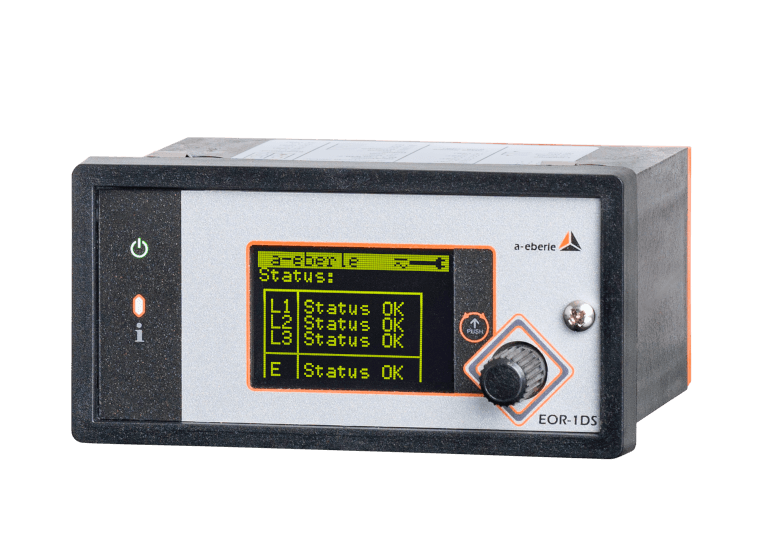
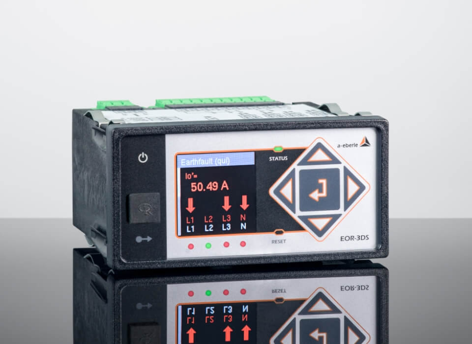
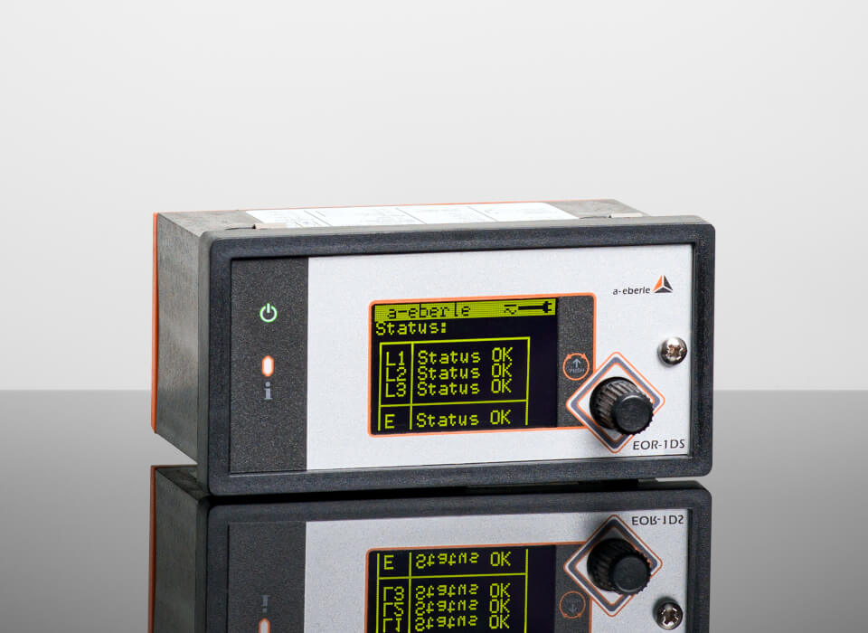
EOR-1DS
- Inexpensive variant with the following locating methods:
- qu2 wiper method
- pulse detection
- Additional short-circuit detection
- Simple operation and parameterization without software
- Integrated Modbus RTU connection
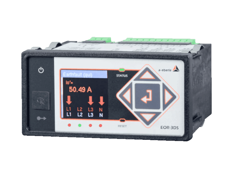
EOR-3DS
- Extensive earth fault location functionality (algorithms such as EOR-D)
- Additional location methods for the EOR-1DS such as:
- qui method for re-igniting faults
- Harmonics method
- Extensive functionality for the intelligent local network station (SCADA, security, switching)
- Can be used as a digitization unit for local substations
Precise earth fault location and comprehensive network analysis
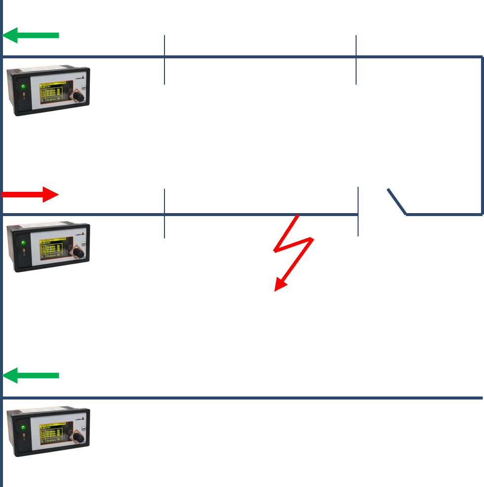
The evaluation of the procedures results in directional information for each monitored line (fault forward / faulty outgoing circuit or reverse / fault-free outgoing circuit). It is possible to localize and find the earth fault from all the displays (see example). The more locating devices are distributed throughout the network, the more precisely the fault location can be pinpointed.
The advanced locating devices from A. Eberle not only provide precise directional information for detected faults, but also enable comprehensive analysis and monitoring of the entire electrical network. By integrating the latest sensor technologies and algorithms, these devices enable continuous recording and evaluation of network parameters. This leads to improved performance in fault detection and enables proactive fault prevention. In addition, the locating devices can also store historical data and identify trends to support long-term network analysis and optimization. As a result, A. Eberle’s products not only provide reliable earth fault location, but also contribute to the efficiency and reliability of the entire power grid.
Earth fault location method
The following section briefly describes the individual methods for localizing the earth fault:
Wiper process
- Response threshold of the zero sequence voltage Uen is adjustable
- Evaluation of the transient process at earth fault inception
- Extremely reliable detection due to integrating evaluation (qu2 method)
- works in both compensated and isolated networks
- in contrast to the “stationary methods”, all earth faults (including short earth fault wipers) can be detected
Qui method
- Extension of the qu2 method to specifically and separately detect re-igniting faults
- Methodology of the qu2 method applied to a sliding observation window and observation of the number of re-ignitions
Reactive current method / sin(φ) method
- Response threshold of the zero sequence voltage Uen is adjustable
- Applicable in an isolated system
- The angle between zero sequence voltage and zero sequence current is evaluated. In the isolated system, it can be easily concluded from this whether the monitored outgoing circuit is faulty (I0 and U0 behave inductively) or fault-free (I0 and U0 behave capacitively)
Wattmetric method (with or without watt residual current increase)
- Evaluation of the residual wattage current, which still flows via the fault location even in the fully compensated grid
- Precise measurement required to determine the angle between I0 and U0 in order to correctly determine the residual watt current
- Consideration of transformer faults possible via parameterization
- Response threshold of the zero sequence voltage Uen is adjustable, response threshold of the residual watt current is adjustable per outgoing circuit
- The residual wattage current can be increased by increasing the residual wattage current (resistor parallel to the compensation coil) in order to simplify the correct determination of the direction of the wattmetric current
Harmonics method
- Response threshold of the zero sequence voltage Uen is adjustable
- Application of the principle of the reactive current method for compensated networks by using higher frequencies (e.g. 250 Hz)
- in EOR-D, harmonic method with comparison of the current values of several outgoing circuits is also possible (comparative evaluation). Otherwise
- It is possible to choose between different harmonics (e.g. 5th – 250 Hz). A free harmonic frequency can also be parameterized
Pulse localization
- By cyclically switching a capacitor or an inductor in parallel to the compensation coil, a pulse pattern is generated in the event of an earth fault, which is then recognized by the locating device
- “Deep localization” down to the fault location is possible
- optionally, a threshold for the zero sequence voltage Uen can be parameterized
- with our EOR-1DS fault indicator , the change in angle caused by the pulsing is evaluated in addition to the amount of current, which is why a specific degree of compensation no longer needs to be maintained for correct detection of the pulse pattern
Advantages of earth fault monitoring
with the combined short-circuit and earth fault indicators from A. Eberle
Welche Vorteile sind durch konstante Erdschlussüberwachung gegeben?
Constant earth fault monitoring is possible with our short-circuit and earth fault indicators:
Constant earth fault monitoring in electrical systems and power grids offers several advantages, including:
- Prevention of outages: Timely identification of earth faults and their rectification helps to prevent or minimize power outages, which ensures continuity of operations in industrial plants and supply to consumers in public power grids.
- Reduction of downtime: The rapid elimination of earth faults due to continuous monitoring results in shorter downtimes, which increases productivity and efficiency in various application areas.
- Cost savings: By preventing major damage and power outages, significant repair costs and financial losses can be avoided.
- Maintenance planning: Monitoring earth faults helps to plan maintenance work, as it continuously monitors the condition of electrical installations and can predict when maintenance work is required.
- Compliance with safety regulations: Earth fault compensation to reduce residual currents and permissible touch voltages as well as continuous earth fault monitoring are usually the optimum solution for complying with the applicable safety regulations in conjunction with an economical mode of operation, particularly in the medium voltage range.
- Data analysis: Continuous monitoring allows extensive data to be collected on the condition of the electrical system. This data can be used to analyze and optimize operation.
- Overall, constant earth fault monitoring helps to increase the reliability and safety of electrical systems, minimize failures and increase operational efficiency. This is particularly important in critical applications and in environments where human safety and environmental impact are of paramount importance.
Worauf kommt es bei Erdschlussüberwachung an?
What is important for earth fault monitoring?
Detection capability: The earth fault monitoring system should be able to reliably detect and report earth faults. A. Eberle devices have a variety of detection algorithms (see above) that can be combined as required. This means that a suitable and reliable solution is always available for different applications (type of network, available measurement accuracy, operating philosophy).
Speed of detection: The monitoring devices should detect and report faults quickly to enable a rapid response and fault rectification before major damage can occur. The wiper method with which our devices work detects the fault within a few 100 ms, the stationary locating methods evaluate the direction of the fault within around one second, with pulse locating it depends on the duration of the set pulse pattern. This means that earth faults are detected very quickly and localization can begin immediately (even if the detection of earth faults is not quite as time-critical as, for example, the disconnection of short-circuits by protective devices).
Locating capability: The system must be able to pinpoint the exact location of the earth fault or leakage current to facilitate localization and repair. All our procedures therefore provide a directional localization message
Alarms: The system should be able to trigger alarms to inform operating personnel or the relevant authorities of the presence of an earth fault. These alarms can be visual, audible or via networks and communication systems. You therefore have a wide range of options for linking to control systems (binary outputs for all A. Eberle fault indicators, Modbus for EOR-1DS, EOR-3DS and EOR-D (various common control system protocols).
Data recording: The monitoring devices should record and store data on detected earth faults and leakage currents to enable later analysis and tracing. Therefore, all A. Eberle locating devices record logbooks and fault records so that faults can be analyzed retrospectively.
Maintenance and diagnostics: The system should have self-diagnostic and self-test functions to ensure that it is working properly and to report maintenance requirements. A. Eberle fault indicators have active status monitoring and reporting in the event of a fault, as well as logbook entries and regular software updates.
Integration into the overall system: Earth fault monitoring should be seamlessly integrated into the overall electrical system in order to enable efficient monitoring and control. Our short-circuit and earth fault indicators are therefore available in various hardware designs.
Remote monitoring: In some cases, it makes sense to be able to monitor the monitoring equipment remotely in order to be able to react to faults even if the operating personnel are not on site. With our flagship fault indicator, the new EOR-3DS, remote access “Management and Operations” is possible via MQTT. With the classic EOR-D, remote access is possible via COM server.
Scalability: Depending on the size and complexity of the network, the earth fault monitoring system should be scalable in order to meet the requirements. With the new EOR-3DS, mass updates and automated management in device groups are possible using MQTT for “Management & Operations”. The device is capable of scaling in large numbers and operating remotely in the network.
Data evaluation and reporting: The collected data should be analyzed and reports created to identify trends and patterns and to contribute to the optimization of operations. Therefore, EOR-1DS and especially EOR-3DS provide a variety of measured values (also MQTT & IoT), which ensure transparency and security in your network.