General Information
The use, setting and effect of the e-coil on the location of earth faults will be described briefly here.
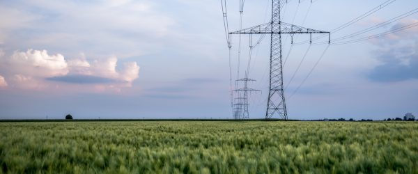
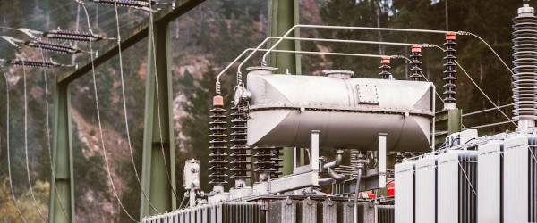
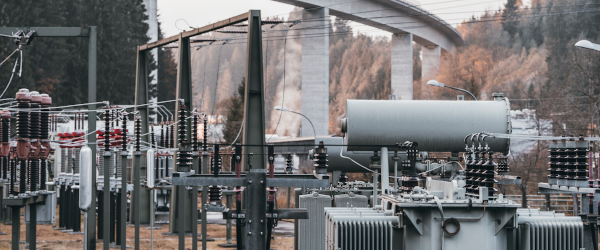
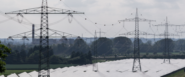
The earth fault compensation coil, e-coil or also called the Petersen coil after its inventor, is connected between the neutral point (zero point) of the network and earth. A network operated like this is called an earth-fault compensated or compensated network. Compensated medium voltage networks are common in German-speaking countries and in other European countries a trend towards this type of neutral point treatment has also been emerging recently.
For more information, see references (1) and (2).
Smaller networks use an e-coil that can be set in stages or is even infinitely adjustable. In larger networks multiple e-coils are used that are either switched in parallel at the feed-in point or are directly associated with individual network areas. Connection to the network is often through its own neutral point.
Neutral-point treatment
The earthing of the network neutral point through an e-coil has no effect on the trouble-free operation of the network. Only in the case of earth faults has the e-coil become important. While with a fixed or low-resistance connection between neutral and earth the single-phase fault is an earth fault and leads to an interruption of the supply, in compensated networks only a small current flows through the fault location. The network can continue to operate and there is usually plenty of time to locate the fault and isolate it by switching action.
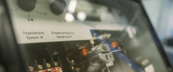
E-coil settings
In undisturbed operation the capacitances between the conductors and earth are never the same. The resulting asymmetric capacitance drives a current through the parallel connection of the e-coil and network capacitances.
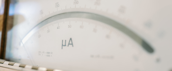
A voltage can be measured in the e-coil that reaches its maximum value at resonance. The resonance curve is determined, adjusted by the e-coil and the voltage measured at its auxiliary winding.
If a current is set at the scale of the e-coil, that is greater than the current resulting from the network capacitance, this is called over-compensated operation; if a smaller current is set, this is called under-compensated network operation. In medium voltage networks, a current, taking into account the local ground conditions (Il – ICe) of up to 25 A is common.
Notes on the current distribution in the network and the corresponding phasor diagrams are included in particular in reference (3).
It is not always easy to set up the e-coil. The high level of symmetry of the cable construction in cable networks generates only a small zero sequence voltage and thus a flat resonance curve.
Installation aids for critical cases are given in references (4) and (5).
Firstly, a description is given of how, by measuring the phase-earth voltages a universal resonance curve can be calculated and secondly it is shown how using asymmetric capacitances the resonance point receives a clearer expression. The required setting at close to the resonance point can thus be made more safely.
In the case of an earth fault, the network capacitance forms a parallel resonant circuit with the e-coil, to which the full neutral point voltage is applied. If the e-coil is set close to resonance, the current through the point of failure remains small and damage at the earth fault location is avoided. The purpose of an earth fault locating device is to find the path of this small current. A setting other than the resonance point of the e-coil increases the current at the fault location and can make troubleshooting easier.
Earth fault detection
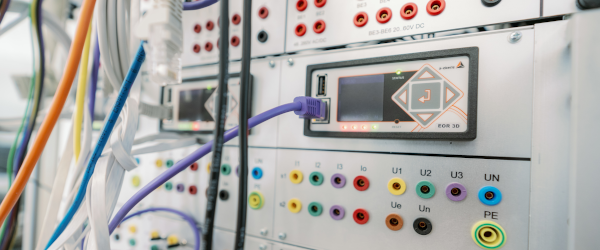
If the load operations have subsided after an earth fault (persistent earth fault), the fault location can be determined with earth fault location equipment. Earth fault locating relays are available on the market that measure and evaluate the effective, reactive and/or harmonic content.
Since the current at the fault location also has to flow through the e-coil, this is the central place to exert an influence on the fault current.
A simple method of earth fault detection is the pulse location principle. In this process, the reactive current in the e-coil is modulated. This current thus identified flows to the point of failure and can be detected on its way from earth fault location relay and displayed.
Maintenance
Switching operations or larger network changes result in a new capacitive earth current of the galvanically connected network and require adjustment of the e-coil. The e-coil can only perform its protective if the setting is checked for such interventions and corrected if necessary.
References:
[1] Sternpunkt
Hubensteiner, H. u.a.: Schutztechnik in elektrischen Netzen Bd. 11993 VDE-Verlag Seite 59 .. 74
[2] Sternpunkt
Handschin, E.; König, D.: Mittelspannungs-Sternpunktbehandlung
Die Grundlagen NMT Tagungsheft Nov.1995, Mulhouse Abschnitt: A.1.
[3] E-Spule allgemein
Speck, D.: Der Netzschutz Neckarwerke Elektrizitätsversorgungs-AG 1981 Seite 14 … 23
[4] Einstellung
Hauser, G.; Rüger, R. und Schelski, U. Düren: Ermittlung der Resonanzkurve mit Hilfe der Leiter-Erd-Spannungen Elektrizitätswirtschaft, Jg. 85 (1986) Heft 11 Seite 427, 428
[5] Einstellprobleme
Schäfer, H. D. u. a.: Erhöhung der Verlagerungsspannung inMittelspannungs-Kabelnetzen mit Erdschluss-Kompensation Elektrizitätswirtschaft, Jg. 93 (1994) Heft 21 Seite 1295 …1302