Compensated Networks
In “compensated networks” the current through the point of failure is minimised with the help of an earth fault compensation coil (e-coil). For this purpose, the e-coil is already in operation in a healthy network, i.e. set without an earth fault so that in the event of an earth fault, the capacitive component of the current is compensated by an inductive current through the fault location. The following figure, Figure 1, shows the network in the case of a single-pole earth fault in Phase L1.
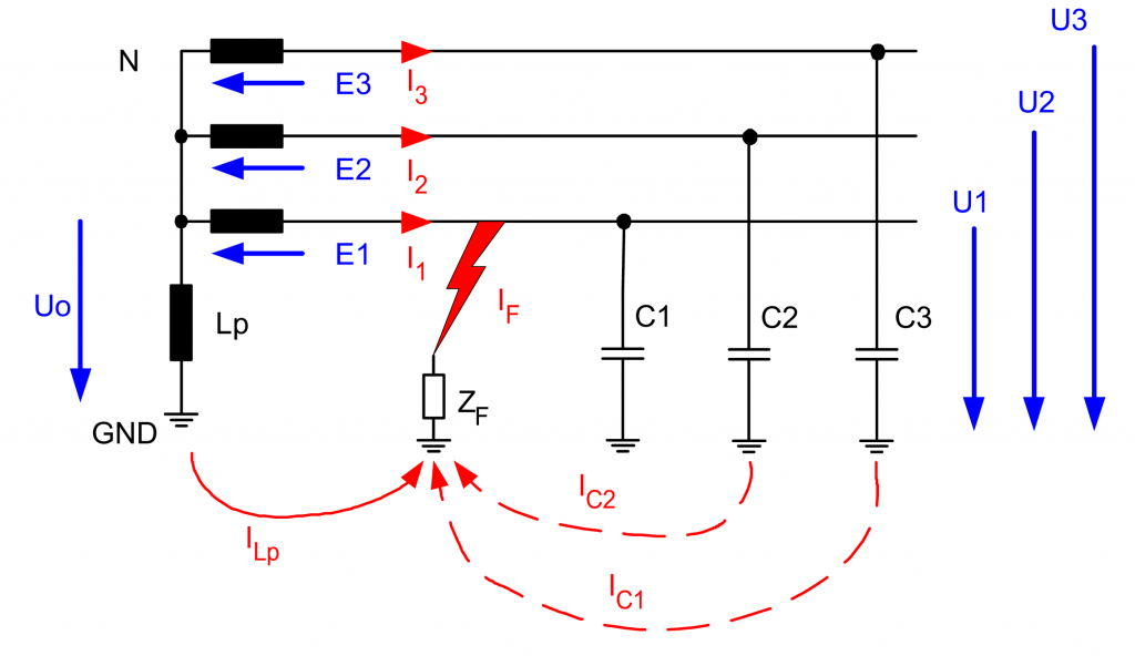
Lp
C1, C2,C3
ZF
N
E1,E2,E3
Uo
IC1, IC2
ILP
IW
IF
E-coil (Petersen coil)
Conductor capacitances of phases L1 to L3
Transmission impedance at the fault location
Neutral point of the transformer
Phase voltages
Zero sequence voltage
Capacitive currents in both healthy phases
Inductive compensation current through the e-coil across the fault location
Active component
Current across the fault location
Objective of the E-Coil
The objective of the e-coil control is now to set the e-coil in the healthy network operation to the desired value already. Several methods are available for the control, wherein the equivalent circuit for the resonance procedure and the location curve procedure can be derived without the use of symmetrical components.
Simplified equivalent circuit
The simplified equivalent circuit diagram should describe the network in the range from the operating state “healthy network” to the operating state “saturated earth fault”. First, for a simpler notation, the capacitances of the network and the inductance of the e-coil are replaced by their complex conductances (admittances). It is assumed that the resistive or capacitive asymmetry in the case of an saturated earth fault is present in only one phase.


