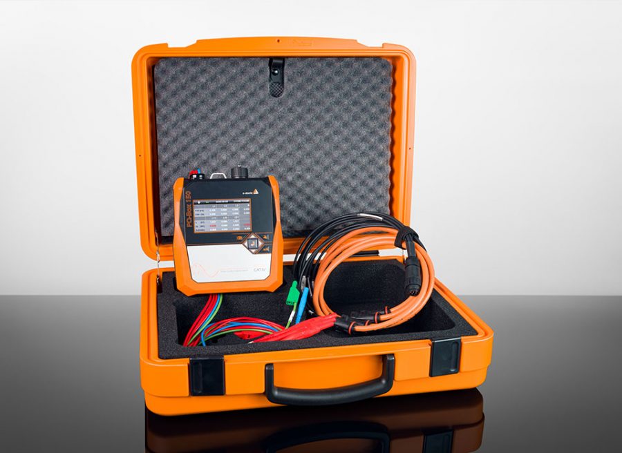
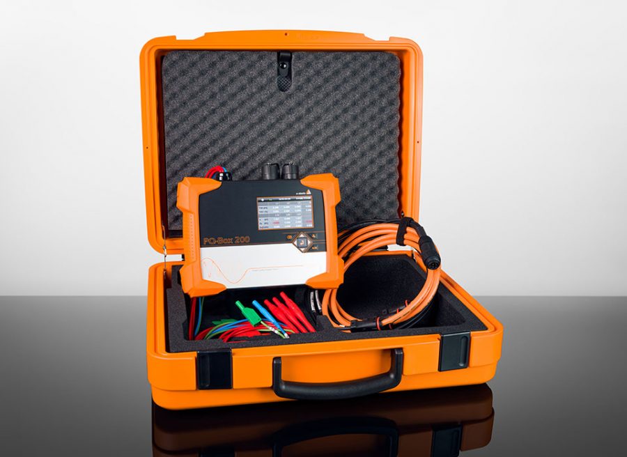
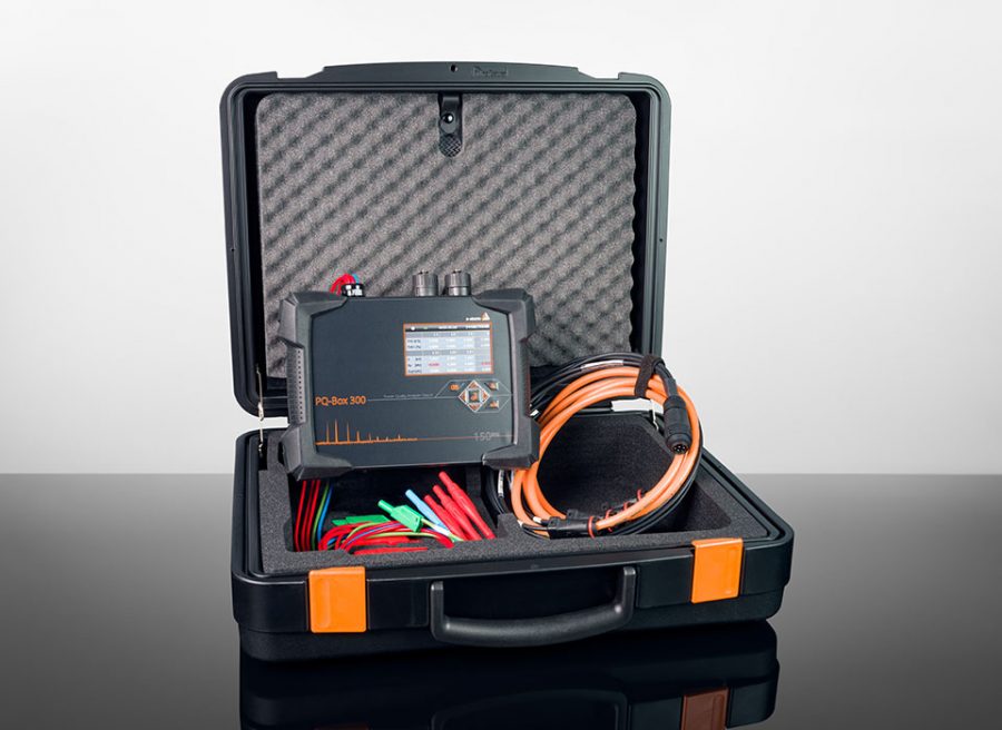
In power quality measurements, odd harmonics such as the 15th, 21st & 27th are often violated. What are harmonics anyway, how does this circumstance occur and what influence does this have on the neutral conductor. This article deals with these questions and sheds light on this matter.
Definition of Harmonics
Due to the increasing number of non-linear consumers, more and more network feedbacks occur which can be characterised by a non-sinusoidal current. The TÜV SÜD defines harmonics as follows:
Harmonics are integer multiples of the mains frequency. They are caused by non-linear loads such as discharge lamps (e.g. energy-saving lamps), overloaded transformers, power supply units with peak-value rectifiers and by the use of power converter valves, e.g. rectifiers, frequency converters, regulators, UPS systems. The characteristic of these consumers and equipment is a non-sinusoidal current or a current flow that is periodically switched on and off. Generators whose winding technology allows the generation of harmonic voltages (harmonic fields) also cause harmonic currents when connected to the mains. These non-sinusoidal quantities can be traced back to sinusoidal quantities using suitable mathematical procedures (Fourier analysis). In addition to the fundamental frequency (in Europe: 50 Hz), they also contain integer multiples, the so-called harmonics. These harmonic currents cause voltage drops at the mains impedances or at the generator impedance. These voltage drops (harmonic voltages) are superimposed on the fundamental frequency (50 Hz) and distort the sinusoidal shape of the mains voltage. As a result, the trouble-free operation of other consumers (e.g. motors, generators, capacitors) can be impaired.
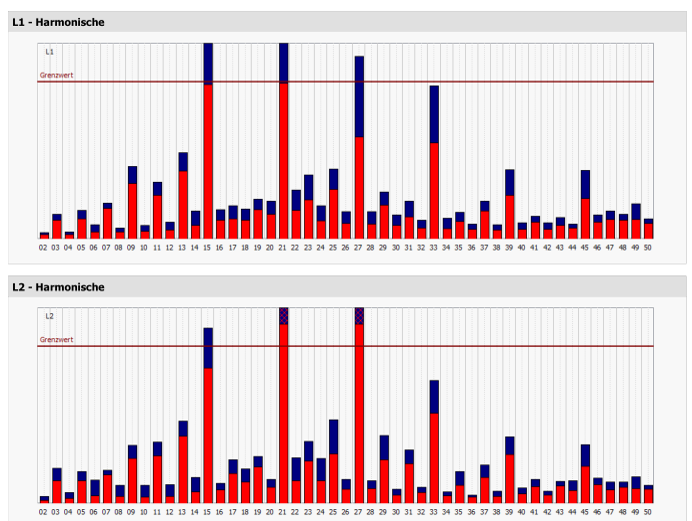
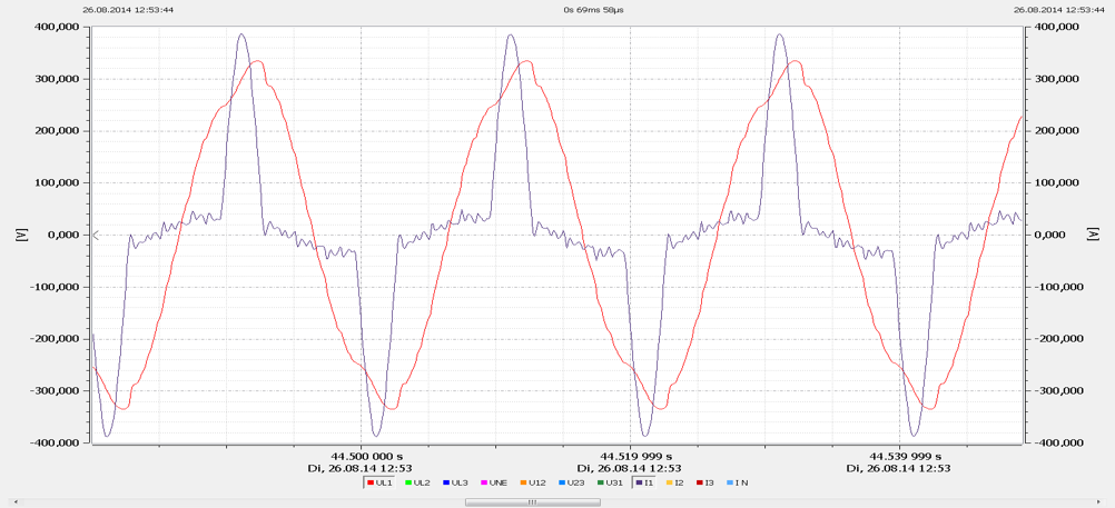
These harmonics can be detected by power quality measurements. Figure 1 shows a typical power quality measurement the case as described above has occurred. At first glance, the harmonics are exclusively odd and divisible by three.
Effects of single-phased devices
Nowadays, more and more single-phase devices are used that are controlled via a switched-mode power supply. In the home area, these are, for example, computers, game consoles and many other household appliances. Nowadays, these devices no longer have a transformer connected upstream, but a switched-mode power supply. In most cases, a bridge rectifier is built into the input of these switching power supplies, which absorbs the current in the form of pulses. In the past, the current was taken up sinusoidal by a resistive load. Figure 2 shows a measurement of the pulse.
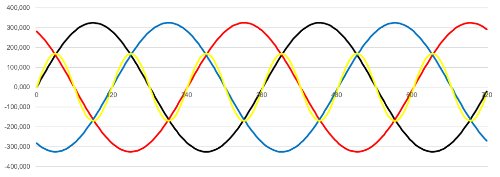
Decomposing the current into its spectrum, all odd harmonics are present. The harmonics divisible by three add up on the N conductor. This is because the phases L2 and L3 are 120° out of phase in the three-phase system. The 120° phase shift is of course also the time shift in which a full sinusoidal oscillation of 150 Hz is carried out as shown in figure 3. It can be seen in the figure that after 120° a full sine wave has been passed through and the next phase L2 then begins. If we now assume that similar loads are installed in the network on all three phases, then the third harmonic of the phase position for phase L2 and L3 would certainly also be in a similar position.
If the load on the three phases L1, L2 and L3 are symmetrical and loaded with 100 A, then the N conductor is not loaded. However, this is only true for the fundamental and for all harmonics that are not divisible by 3. If you can measure 10 A on all phases for a fifth harmonic, then you could also see only 0 A on the N conductor. The third harmonic has a special feature: since the initial position is exactly 120°, all samples of the phases L1, L2, L3 and N conductor must add up to 0. If the phases overlap exactly, this means that three times the current must flow on the N conductor. This circumstance also applies to the double and triple frequency, as well as the sixth or ninth harmonic. However, it is the case that mainly odd-numbered harmonics are found during investigations in the network and even-numbered harmonics hardly occur as a rule.
Effects of current harmonics on the electrical grid
In conclusion, it can be stated that current harmonics with an ordinal number divisible by three overlap to a triple magnitude with symmetrical loading in the neutral conductor. This poses a problem for the network in that the impedance of the network for the harmonics divisible by 3 is four times as large as for the fifth harmonic or the fundamental. With symmetry, no current flows from the fifth harmonic on the N conductor, but three times the currents can be measured from the third harmonic, which flow back to the transformer. Therefore, for the harmonics divisible by 3, it is always quite decisive at which point in the network these harmonics are evaluated in the network. In the case that measurements are made relatively close to the transformer, a harmonic divisible by three is usually very inconspicuous here. However, the further one moves away from the transformer towards the consumer, the harmonics divisible by three increase rapidly on the voltage: much faster than a fifth or seventh harmonic would do.
The trend towards grids with higher-loaded harmonics cannot be prevented due to the large number of single-phase devices. All these devices increase the level of the harmonics divisible by three, such as the 3rd, 15th or 21st harmonic. In the meantime, the standards have reacted and increased the compatibility levels that are permitted for the public grid. For example, the compatibility level in the current EN 50160 for the 15th harmonic has been increased from 0.5 % to 1.0 %. If power quality assessments are carried out nowadays, the stored limit values in the measuring devices should be correctly set to the currently valid limit values
Author
Jürgen Blum, Product Manager Power Quality Mobile

