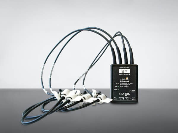
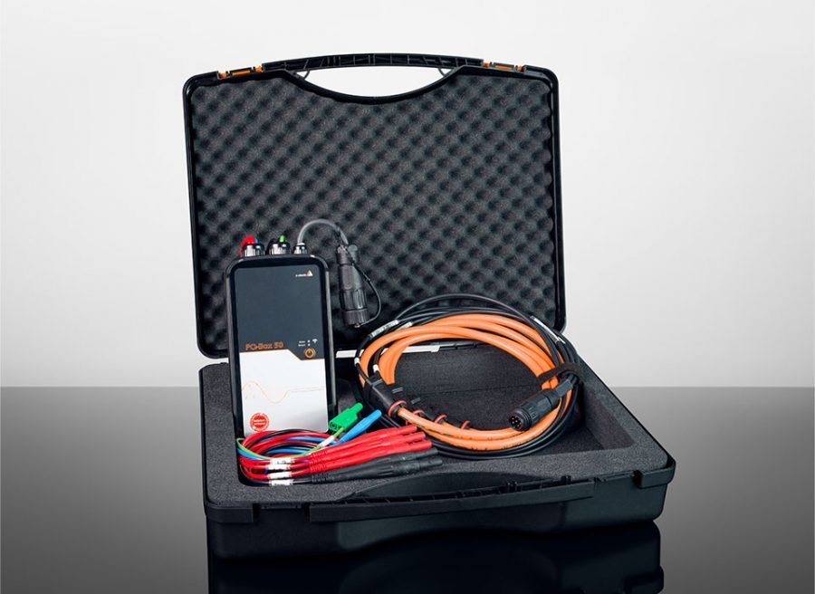
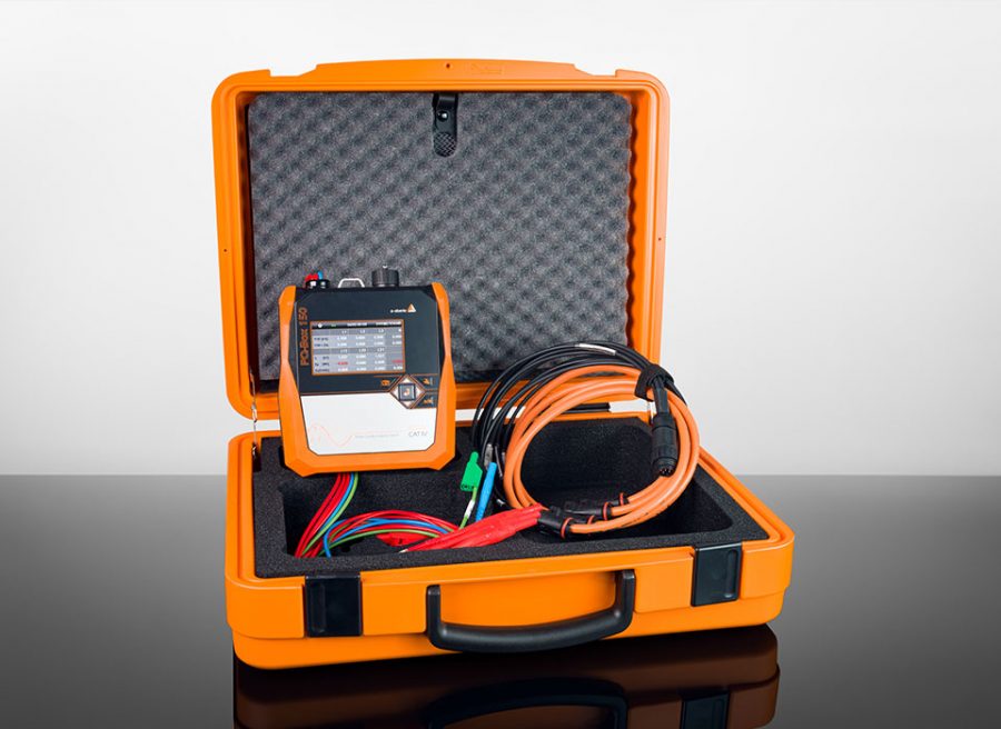
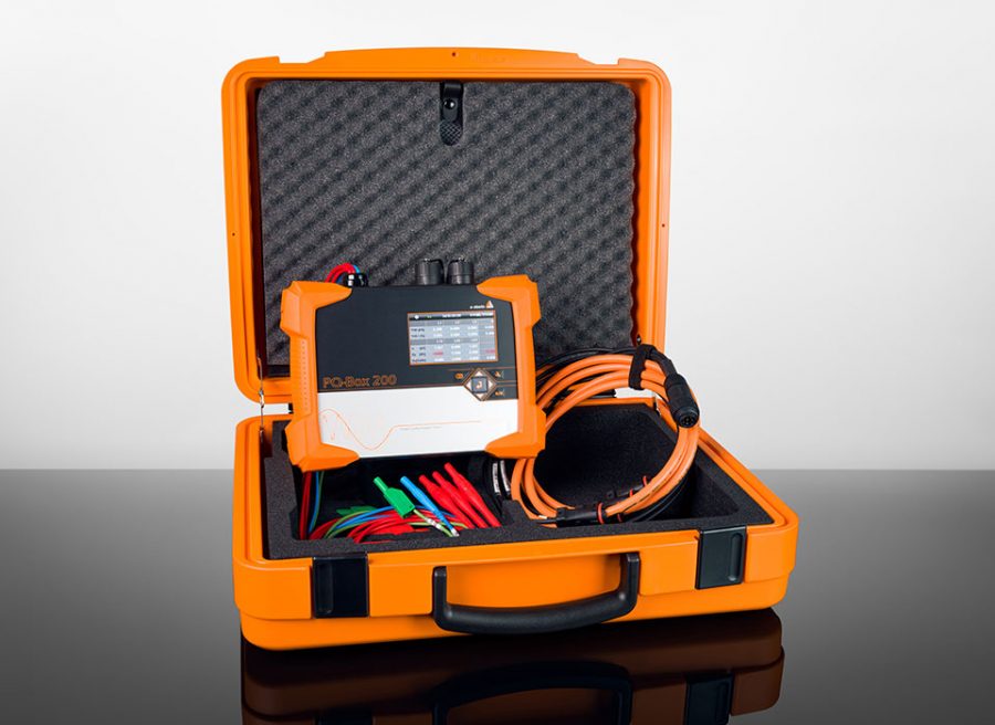
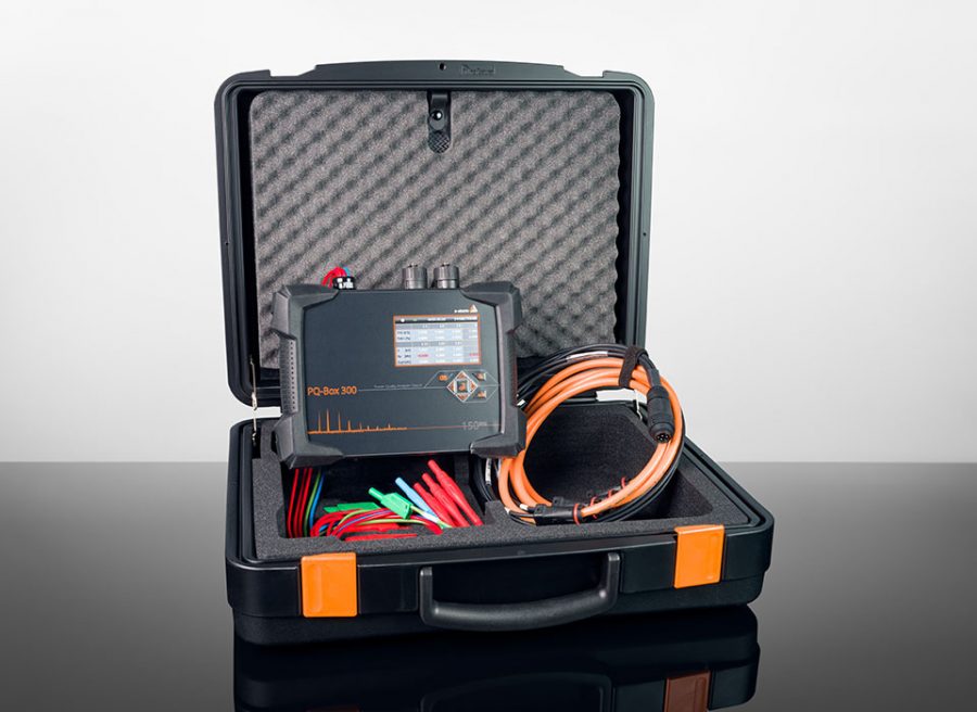
The transformation of the energy industry from a centralized structure to a decentralized energy supply is creating complex energy networks with volatile load flows and changing load flow directions. Grid feedback effects must be reduced to a tolerable level to avoid negative effects. In this context, conventional respectively non-conventional converters and power quality measurement technology are converging to form an innovative and economical „system solution“ with a view
to the future.
The transformation in the generation, transport, distribution and consumer structure of Central European energy grids is gathering pace, also in other parts of the world. For example, in Germany, the federal government‘s coalition agreement provides for the phase-out of coal-fired power generation by 2030, while the nuclear phase-out is still to be decided. In addition, the federal states are to make 2 % of the land available for wind energy. In parallel, solar energy on the roofs of new commercial buildings will become mandatory.
This means that the extensive power plants representing centralised energy production will gradually be replaced by numerous smaller, decentralised producers. These usually feed into all grid levels from the low-voltage house connection to the extra-high voltage grid with the help of power electronic components. On the other hand, more and more consumers on the market have also installed power electronic elements as part of energy efficiency improvements. This leads to a complex energy grid with volatile load flows and changing load flow directions. Furthermore, the non-linear characteristic of the power electronic components leads to so-called grid repercussions in the energy grids and is the leading cause of higher-frequency voltage and current components in energy grids.
The change in mains feedback, such as harmonic voltages/currents and flicker, must be limited to a tolerable level to avoid disturbances. The producer and consumer structure result in numerous transfer and clearing points, which are neuralgic points with regard to ensuring voltage quality.
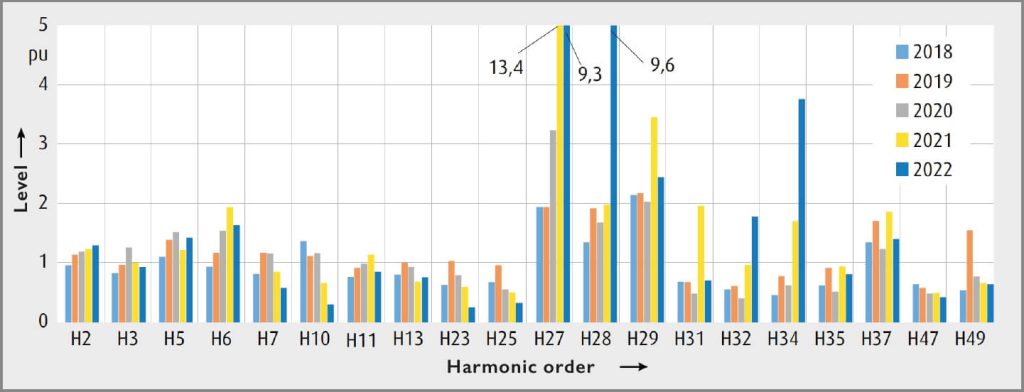
The following example, taken from a measurement at TenneT in the transmission grid, shows the change in individual harmonic levels over five years compared to 2017. The maximum 95 % quantiles of a week were compared. The first year in this comparison was assigned 1 pu. Figure 1 only shows the harmonic orders with measurement levels relevant for evaluation. It can be seen that significant changes in the measurement levels can result from changes in the grid, such as the new connection of power electronic components or a change in the grid topology.
To determine harmonic levels and the THD factor (Total Harmonic Distortion), power quality measuring devices are required that already record higher-frequency voltage and current components up to the supraharmonic (higher frequency emissions > 2 kHz) range. Furthermore, these devices can support interference analysis, e.g. using built-in transient interfaces with a sampling rate up to 40.96 kHz.
In addition to the increase in harmonic emitters mentioned in the introduction, every power grid also has parallel and series resonances that alternate with increasing frequency, starting with parallel resonance. Harmonics can excite these systems, leading to significant disturbances such as noise, damage to equipment or interactions with power electronic equipment.
Practical experience shows that the phenomena as mentioned above occur more frequently. This is due among other things, to the changed generator and consumer structure but also to the addition of partial cabling sections.
A defined transmission behaviour of the installed current and voltage transformers is an essential requirement for troubleshooting and monitoring the limit values. Basically, PQ standard measuring devices must provide court-proof but also traceable data. Therefore, the measuring instrument standard IEC 61000-4-30 for class A instruments fully describes the aggregation and accuracy of the measurement data. The accuracy of the measurement inputs must be <0.1 %, and that
of the harmonic measurement <5 %.
The entire measurement chain must be observed
The link between the PQ meter and the energy grid is the conversion of the current and voltage signals. Conventional current and voltage transformers tested according to IEC 61869-2, -3, -4 or -5 are often used. The problem is that these transformers are designed and tested for operation at nominal frequency. Thus their frequency transmission behaviour does not allow accurate detection of higher-order harmonics and supraharmonics. Accordingly, the transmission ratio‘s frequency dependence is often not considered.
However, this procedure involves significant uncertainties since precise statements about the frequency-dependent transmission ratio can only be made using complex measurement procedures, often only after disturbances have occurred. The question thus arises as to which technology of primary devices can be used to perform an adequate voltage measurement over a vast frequency spectrum.


While current transformers, as shown in figure 2, have a relatively broadband frequency response, this is severely limited,
especially in the case of inductive voltage transformers, due to the natural resonance points, so that they do not meet the requirements for power quality measurement. In addition, these natural resonance points move closer to the mains frequency as the system voltage increases so that the suitability for PQ measurement is more limited (see IEC/TR 61869-103). This results in the requirement for an alternative measurement principle. Resistive capacitive voltage dividers, RC-dividers for short, are suitable for this purpose due to their excellent frequency response and are mostly used in extra-high and high-voltage networks. Properly tuning these primary components with the electrical quantities shown in figure 4 makes it possible to achieve an accuracy class of 0.2 in the frequency range from 0 to 10 kHz.
Resistive-capacitive voltage dividers, RC dividers for short, are suitable for this purpose due to their excellent frequency response and are mostly used in extra-high and high-voltage networks.
By matching these primary components with the electrical measurement quantities shown in Figure 4, it is possible to achieve an accuracy class of 0.2 in the frequency range from 0 to 10 kHz.

Functionality of RC-dividers (Resistive Capacitive Voltage Dividers)
RC-dividers consist of a network of serially connected RC elements. The voltage is evenly distributed along the insulator by the components R1 and C1, resulting in a linear voltage distribution.
Does the question arise whether a pure capacitive divider (C-divider) or a pure resistive divider (R-divider) would not suffice?
To perform a very broadband measurement, neither the one nor the other „simple“ divider is suitable. A C-divider cannot measure DC voltage, and the R-divider can have a significant inaccuracy with AC voltage signals due to the parasitic earth leakage capacitances CE, which depend on the size. The combination in the form of the RC-divider is, therefore, ideally suited for use in measuring DC, AC and mixed voltages.
Due to the electrical properties already explained, RC-dividers are suitable for a wide variety of applications:
- Measurement of DC offset in the AC grid
- Measurement of ferroresonances or subharmonic components in the network
- Measurement of harmonic frequencies (PQ monitoring)
- Measurement of transient voltage curves
Other areas of application are:
- Ferroresonance critical points in the network
- Situations with high transient voltage loads and steep du/dt values
- Networks with high frequency variations as a replacement for capacitive voltage transformers
- As an alternative to capacitive voltage transformers for discharging lines, but with long discharge times compared to inductive voltage transformers
The further development of the applicable standards, such as DIN EN 61000-2-2, in the direction of a measuring range of up to 150 kHz will further tighten the future requirements for the measuring equipment. However, RC-dividers can already fulfil this requirement well today, as they can cover a measuring range of up to 170 kHz and higher in combination with suitable measuring devices whose input impedance is 10 MOhm, for example. Furthermore, additional extensions of the frequency range, as well as new measurement tasks, are to be expected or are already in the pilot phase.
Power quality measurements in the transmission grid of TenneT
For example, at the transmission system operator TenneT, more and more non-linear generators and consumers such as HVDC, STATCOM, battery plants, electrolysis plants and wind farms are already being connected to the extra-high voltage grid today and will be increasingly so in the future.
The VDE-AR-N 4130 Technical Rules for the Connection of Customer Installations to the Extra High Voltage Grid and their Operation (TAR Extra High Voltage) and the VDE-AR-N 4131 Technical Rules for the Connection of HVDC Systems and Generation Installations Connected via HVDC Systems (TAR HVDC) require upper limits for the feed-in of harmonic components and components in the harmonic frequency range up to 9 kHz at the grid connection point. In addition, the permissible emissions must be coordinated between the subscribers, and verification must be carried out using suitable procedures.
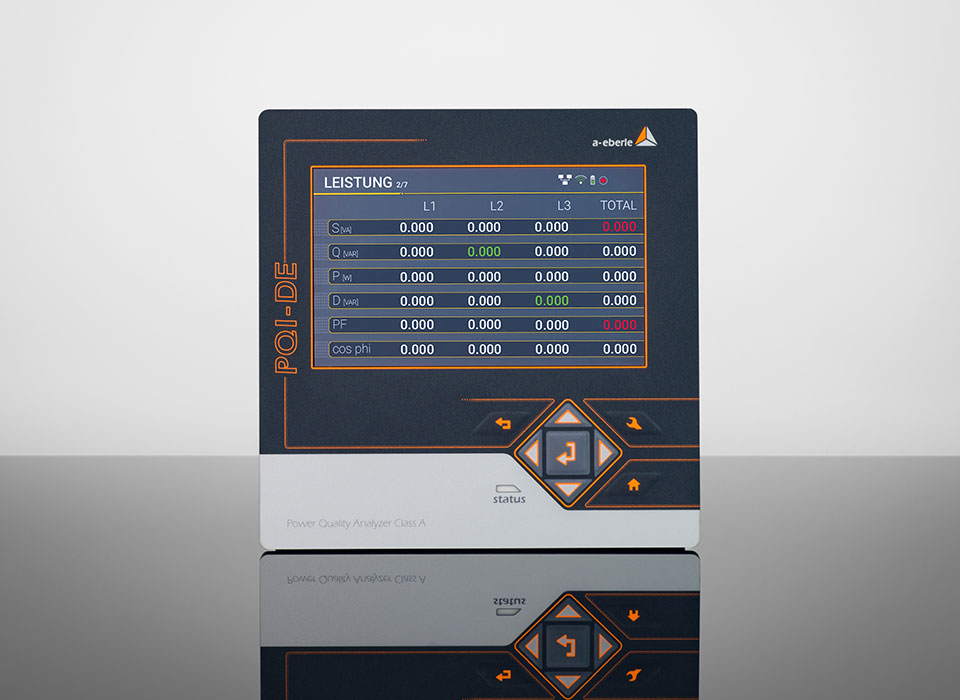
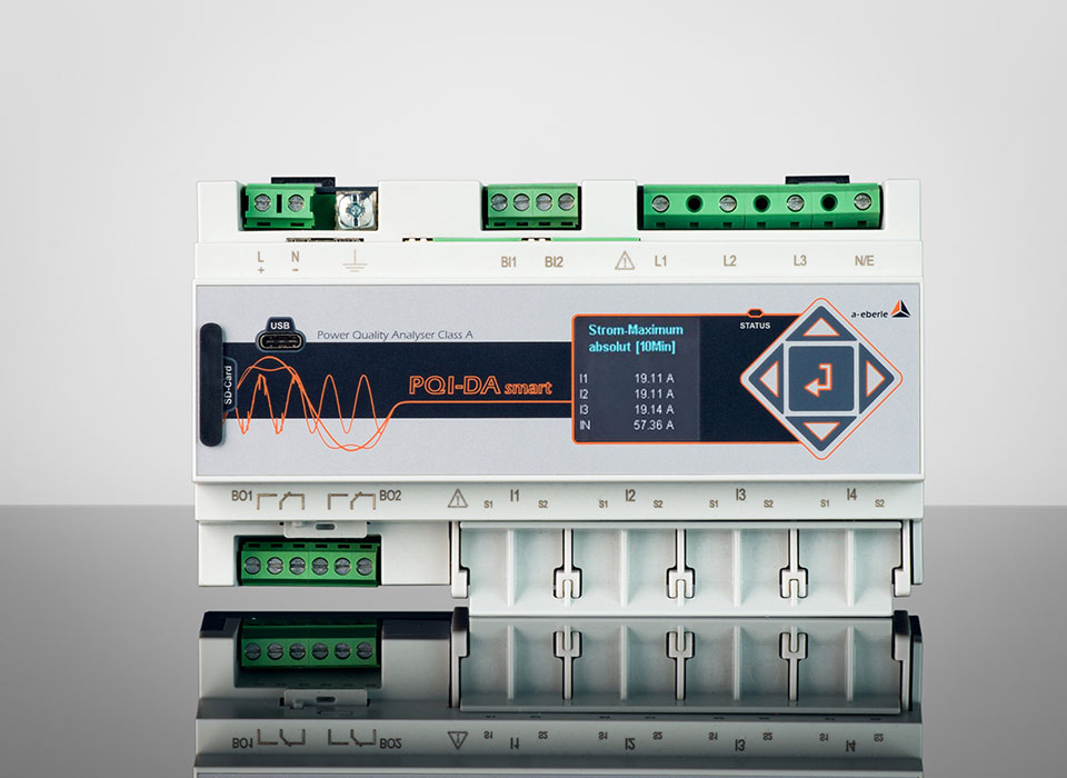
Today, this measurement at the network node with non-linear generators and consumers is carried out using permanently installed RC-dividers and PQI-DA smart (or PQI-DE) power quality measuring devices. The impedance of the two devices is matched to each other, including the measured signal cable length, to obtain the best possible measurement accuracy. Furthermore, there are more and more temporary measurement tasks in the extra-high voltage grid with increased accuracy for power quality measurements or for recording transient switching processes.
These are for example:
- Determination of background harmonics for the coordination of harmonics in the planning phase of projects with new connections of non-linear generators and consumers
- Commissioning of new types of equipment
- Temporary investigations in the context of commissioning new network sections
TenneT already has two mobile metering systems in use for this purpose.
These mobile measuring systems consist of an RC-divider mounted on a trailer and a unique superstructure with the installed measuring and communication technology for connection to the communication network. This, in combination with the pre-assembled connection cables, allows a measurement of equal quality compared to the permanently installed measurement system.
Figure 5 shows the mobile RC-divider from PFIFFNER Messwandler in practice, Figure 6 shows the measuring devices PQI-DA smart and PQI-DE from A. Eberle in the system network for recording the power quality.


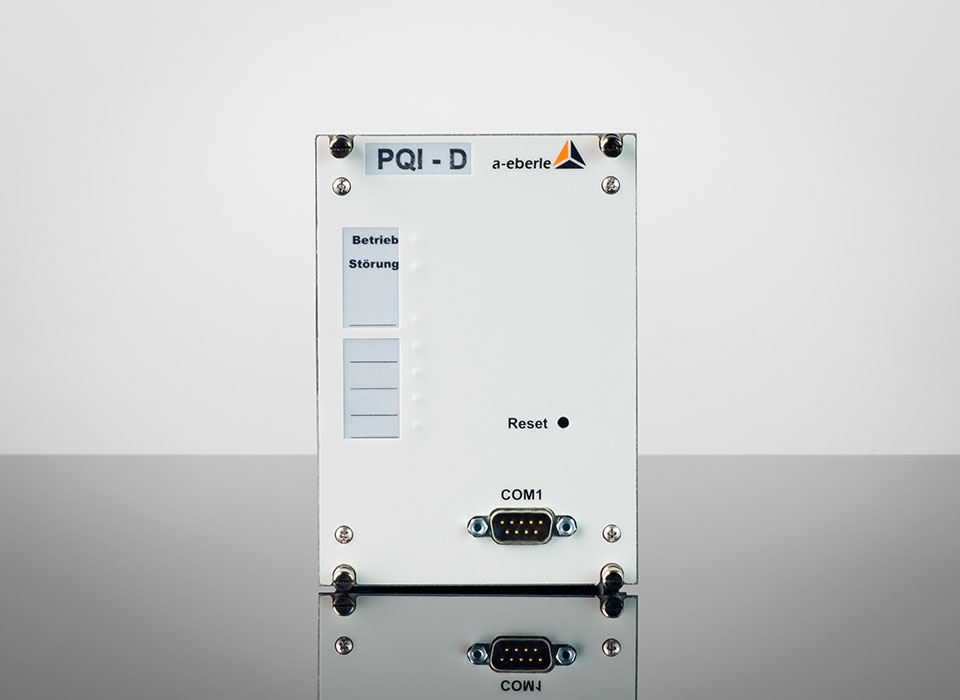
The permanently installed fault recorders and power quality network analysers PQI-DA smart and PQI-DE are the central components in a system that can be used to solve all measurement tasks in a low, medium and high and extrahigh voltage network.
The analysers can be used as disturbance recorders with up to 40.96 kHz sampling rate as power quality measuring instruments according to
EN 50160 / IEC 61000-2-2/4 or as power analysers. Above
all, the components are suitable for monitoring and recording special reference qualities or quality agreements between the energy supplier and its customer and making them available for evaluation or storage.
Modern voltage quality measuring instruments work according to the IEC 61000-4-30, Ed. 3 (Class A) standard. This standard defines measurement methods to provide a comparable basis for the user.

of power quality
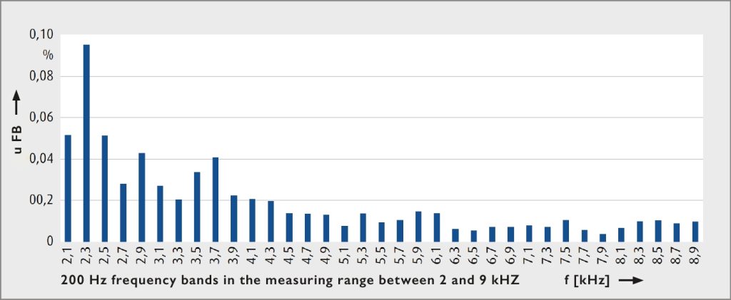
The following example from a measurement campaign with the described mobile measurement system shows measurement results of the 200 Hz bands in the frequency range above the 40th harmonic up to 9 kHz according to the measurement procedure of DIN EN 61000-4-7.
A. Eberle and PFIFFNER Messwandler, naturally in teamwork with energy suppliers such as TenneT, recognised the signs of the times early on and acted accordingly. As a result, the course for future-proof solutions has been set.
Brief introduction of the companies
A. Eberle GmbH & Co. KG
A. Eberle GmbH & Co. KG has established itself as a premium supplier in the field of electrical power, especially in measurement and control technology, since its foundation in 1980. The products manufactured are used at all voltage levels by energy suppliers, grid operators and in industry.
A. Eberle‘s product portfolio includes voltage regulation of transformers with tap changers, fast voltage regulation in the low-voltage grid, regulation of Petersen coils and the associated earth fault location, as well as mobile and fixed-installation voltage quality recording with fault recording and its evaluation.
A. Eberle reacted to the requirements for measurement technology explained below at an early stage several years ago. All power quality devices are designed to be able to measure the supra-harmonic range to meet tomorrow‘s requirements today.
PFIFFNER Messwandler AG
PFIFFNER Messwandler is a medium-sized, family-owned company in Hirschthal, Switzerland. With around 200 employees, PFIFFNER Messwandler develops, produces and distributes low to high voltage instrument transformers for the whole world.
As PFIFFNER International with the brands PFIFFNER, MOSER GLASER, HAEFELY and ALPHA-ET, they have been present as a group of companies in the market for energy technology and electric railways for many years, and since 2021 also with HAVECO in the field of network and plant construction.
The group employs around 900 people and has eight production facilities, four of which are in Switzerland and the others in Germany, Turkey, Brazil and India.
TenneT TSO GmbH
TenneT is responsible for the operation, maintenance and expansion of the extra-high voltage grid in large parts of Germany and the Netherlands. This makes us Europe‘s first cross-border transmission system operator for electricity.
We connect power plants to the grid and ensure a reliable and secure supply of electricity – 24 hours a day, 365 days a year. As the first cross-border transmission system operator, we plan, build and operate an almost 24,500 km long high and extra-high voltage network in the Netherlands and large parts of Germany and enable the European energy market with our 16 interconnectors to neighboring countries.
With sales of €6.4 billion and total assets of €32 billion, we are one of the largest investors in national and international electricity networks, onshore and offshore. Every day, more than 6,500 employees give their best and, in line with our values of responsibility, courage and connectivity, ensure that more than 42 million end consumers can rely on a stable supply of electricity.
Authors
Tobias Engelbrecht, Technologist FACTS and Power Quality, Asset Management Power Electronics Systems, TenneT TSO GmbH
Raphael Wyder, A. Eberle Switzerland AG / Former Business Unit Head PFIFFNER Messwandler AG
Till Sybel, Managing Director A.Eberle Africa (Pty) Ltd.

