Table of contents
What is apparent power?
Apparent power is a term used in electrical engineering to describe the apparent power in an alternating current system. It is made up of the active power (the power actually used) and the reactive power (the power not used for work). The unit of apparent power is the volt-ampere (VA). Apparent power is often considered in complex alternating current circuits in which alternating current flows through electrical devices. It is mathematically calculated as the square root of the sum of the squares of active power and reactive power.
Official definition: According to the IEEE (Institute of Electrical and Electronics Engineers), apparent power is defined as “the vectorial sum of active power and reactive power.” (Source: IEEE Standard 100, “The Authoritative Dictionary of IEEE Standards Terms”)
What is complex apparent power?
The complex apparent power is a representation of the apparent power in complex number format. In this format, the active power is represented as the real part and the reactive power as the imaginary part. In mathematical terms, the complex apparent power can be written as S = P + jQ, where S is the complex apparent power, P is the real power and Q is the reactive power. This representation is particularly useful when analyzing AC circuits.
Official definition: There is no specific official definition for complex apparent power, but it is used in electrical engineering as a mathematical representation of apparent power in complex number format.
What is the difference between apparent power and active/reactive power?
To understand the difference between apparent power, active power and reactive power, let’s look at them as the different components of electrical power. Imagine that the total power is like a beer glass representing the different types of power.
Apparent power (S):
Apparent power is the apparent power generated by an inverter. It is the combination of active power and reactive power. Comparable to the beer in the glass, the apparent power represents the total volume of the drink in the glass.
Active power (W):
The active power is the actual use of electrical energy and is measured in kilowatts (kW). In the beer glass, the active power corresponds to the actual beer you can drink – it is the amount you actually use.
Reactive power (Q):
Reactive power is the unconverted energy in a system and is measured in kilovolt amperes reactive (kVAR). In the beer glass, reactive power would be comparable to the foam on the beer – it adds volume to the glass but has no direct benefit.
To illustrate the relationship, consider the beer glass, which visualizes the relationship between apparent power, active power and reactive power.
To summarize, electrical power consists of three main components: apparent power, the total power in the beer glass; active power, the actual usable beer; and reactive power, the foam, which has no direct function.

What is apparent power in relation to inverters?
For inverters and electrical systems, it is crucial to understand these terms in order to optimize the efficiency and performance of photovoltaic systems. In photovoltaic systems, inverters convert the direct current generated by the solar cells into alternating current suitable for domestic use. Apparent power plays an important role here, as it represents the total power generated by the inverter. An understanding of active power and reactive power is crucial to ensure that the apparent power is used efficiently and that the photovoltaic system functions optimally. Therefore, knowledge of these terms is of great importance not only for technicians and engineers, but also for operators of solar installations in order to maximize the performance and efficiency of their systems.
How is the apparent power calculated?
The formula
The apparent power is calculated using the following formula:
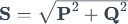
Here:
- S for the apparent power in volt-amperes (VA),
- P for the active power in watts (W),
- Q for the reactive power in volt-amperes-reactive (VAR).
This formula is used to calculate the apparent power in alternating current systems. The unit of apparent power is VA (volt-ampere).
To calculate the apparent power in three-phase systems, the formula for electrical power can be extended by the factor:

Here, U is the voltage and I is the current in the three-phase system.
The following formula can be used to convert the apparent power into active power:

Here ϕ stands for the power factor, which indicates the ratio of active to apparent power. The active power P is also measured in watts (W).
To calculate the apparent power from the active power, the formula can be rearranged:

To calculate the complex apparent power, the complex power S can be represented as the sum of active power P and reactive power Q:

Here j is the imaginary unit. This formula allows the apparent power to be represented in complex number format.
Apparent power illustrated using practical examples
Photovoltaic (PV) system: Apparent power plays a central role in a PV system. The apparent power refers to the combined active and reactive power generated by the photovoltaic modules. Determining the apparent power is crucial for the correct dimensioning of the inverter. An efficient inverter must be able to handle the entire apparent power of the PV system in order to optimally feed the energy into the grid.
Three-phase systems: In three-phase systems, which are frequently found in industrial plants and larger buildings, determining the apparent power is of great importance. In particular, devices with inductive or capacitive loads, such as motors, transformers or capacitors, generate reactive power. The apparent power therefore provides information on how much electrical power is actually required in the system.
Star-connected inverters: The apparent power is a relevant parameter in applications with inverters, especially star-connected inverters. Star connection, also known as delta connection, refers to the way in which the phases of three-phase devices are connected. The apparent power is used here to calculate the total power in the system and to ensure that the inverter can convert it efficiently.
Relevance of apparent power: The determination of apparent power is particularly relevant in cases where inductive and capacitive loads are present. Inductive loads, such as those found in motors, generate reactive power, while capacitive loads, such as those found in capacitors, can absorb reactive power. Apparent power enables more precise dimensioning of components and more efficient energy transmission in electrical systems.
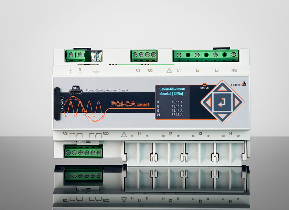
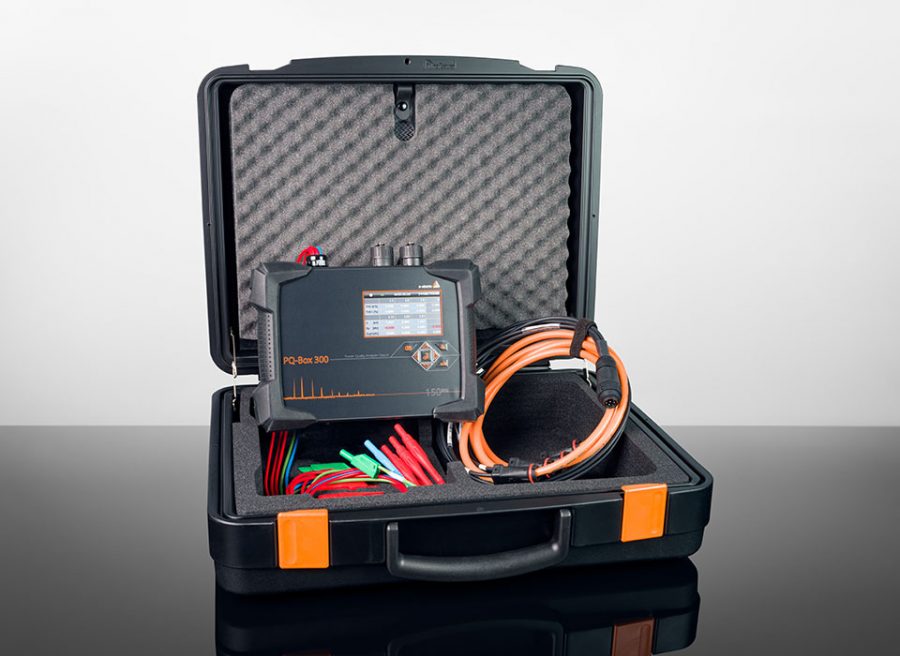
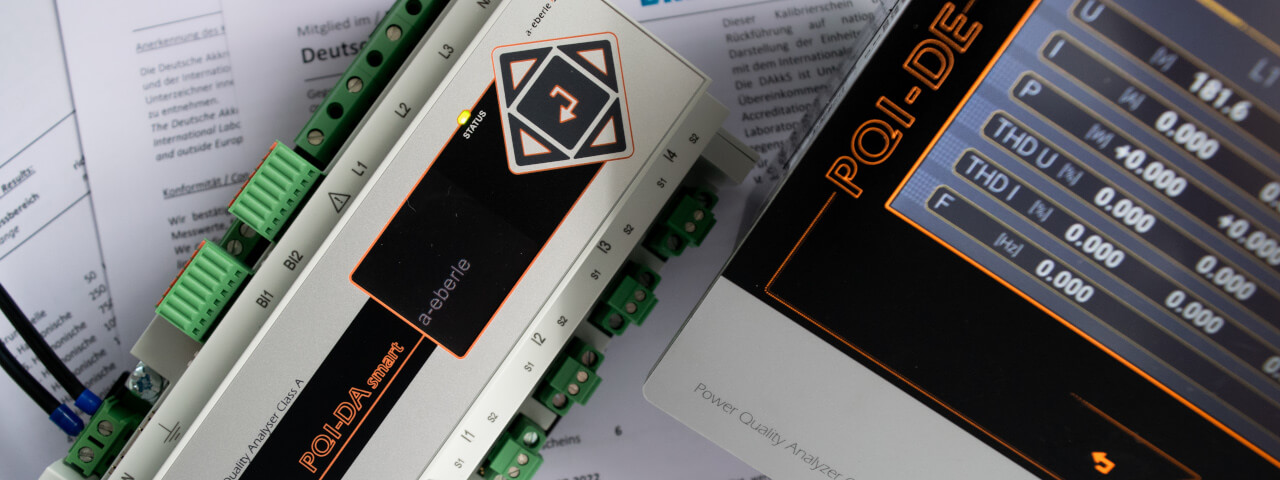
With our power quality analyzers, you can not only determine active, reactive and apparent power, but also carry out a high-quality grid analysis and power quality monitoring. Bring transparency to your grid with class A measuring devices from A. Eberle: