Ferrari´s Meter vs. Electronic Meter

Analysis of a power measurement at a large industrial customer

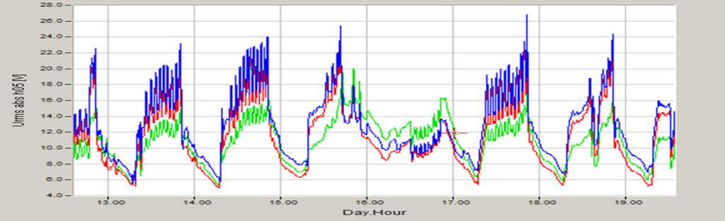
In this technical report, the analysis of a power measurement at a large industrial customer is performed. The customer experiences very large fifth harmonic currents and voltages during production time, resulting in poor power quality. The fifth harmonic reaches up to 26 volts and represents more than ten percent of the total power.

Backgrounds

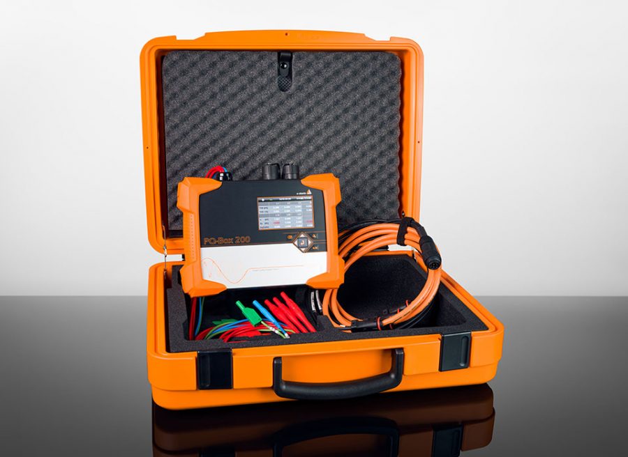
The background to the measurement arises from a situation where a utility had built a new station and operated two energy meters in series for a period of two months. The old station had a Ferrari´s meter, while the new station had an electronic meter. When energy was measured in parallel, it was noticed that the electronic meter was counting eight percent less energy than the Ferrari´s meter. After further testing and recalibration of the meters, it was determined that this large discrepancy remained. To clarify this discrepancy, a power quality measurement was performed (see Figure 1).

Figure 1: Fifth harmonic of an industrial customer during production time on 400 amps current and 26V voltage

Network analyzers enable the quantification of harmonics

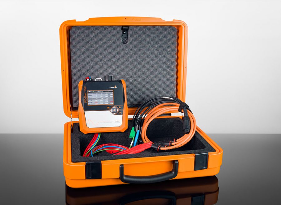
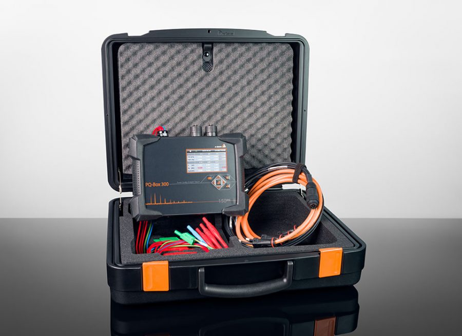
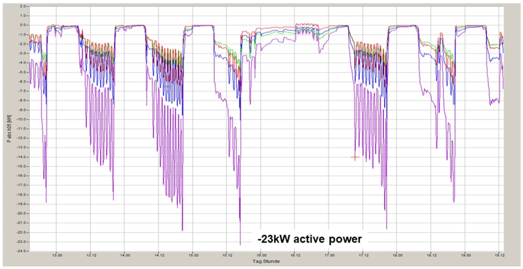
Our mobile power analyzers from the PQ Boxes family allows to quantify the voltage and current of these harmonics, taking into account the phase angle Phi. With this information, it is possible to accurately calculate the active power. The subsequent plot (Figure 2) illustrates the calculation of the active power using the measured data. The graph shows the active power of the individual phases and the three-phase power of the fifth harmonic (250 Hz). The analysis results in an active power of -23.3 kW. According to the definition, a negative value corresponds to a recovery of 23 kW of active power into the upstream grid on the part of the industrial customer at a frequency of 250 Hz.

Figure 2: Calculation of active power, single-phase power and three-phase power of the fifth harmonic

Measurement data analysis

Figure 3: Active power of the fundamental oscillation

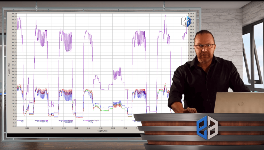
In the present measurement data, the customer’s total power is positive, which refutes the assumption of an incorrect connection configuration. The visual representation shows sum active power positive, while the fifth harmonic runs in the opposite direction with a negative sign (Figure 3).

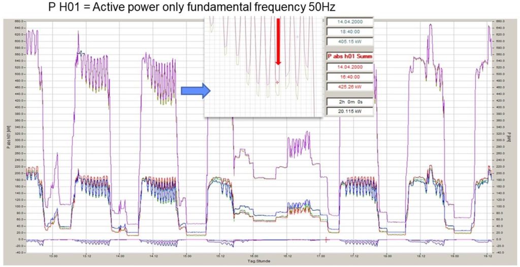
Is it necessary to subtract this harmonic active power quadratically from the sum active power? In this context, there is no need for a quadratic summation of the harmonics for the power calculation. Using the total power, the power of the fifth harmonic can be subtracted directly. This approach is in line with the possibilities offered by modern power analyzers and allows a precise quantification of the harmonic influences on the power level (Figure 4).

Figure 4: Calculation of the broadband active power

The graph in Figure 5 illustrates a level-time diagram showing the progression over a week. The two different colors in the graph represent the total power. The larger power value in purple shows the fundamental active power, while the smaller active power shows the broadband active power (i.e. including all harmonic powers).

Figure 5: Range of total power with indication of total power (blue) and active power (red)
Figure 6: Level time diagram of the total power

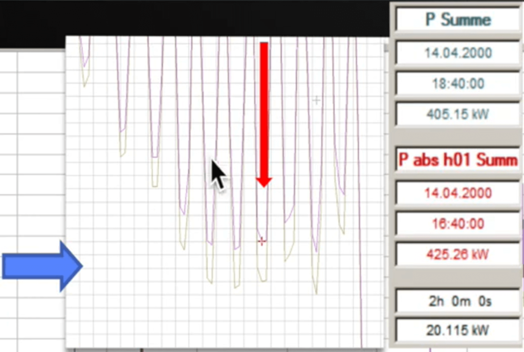
This customer draws a larger fundamental active power from the power grid and simultaneously introduces an active power of the fifth harmonic component in the opposite direction. This simultaneous influence causes the total sum of the broadband power to be slightly reduced. The discrete deviation between these two calculations of power thus represents the resulting difference of the two numerators (Figure 6).

In this context, the question arises as to the precise operation of the various types of meters. An electronic meter records not only the fundamental oscillation but also the harmonic powers. Rather, it acts like a power analyzer by calculating the power that has occurred based on the sampled voltage and current values. These readings produce a power curve, and depending on the sampling rate of the meter, accurate detection is usually up to half of that sampling rate. It is worth mentioning that a correct consideration of the flow direction of a harmonic component is done automatically by including appropriate deductions in the calculation, especially if the flow direction is oriented opposite to the main component.

A Ferrari´s meter, on the other hand, is usually specialized to measure the fundamental vibration active power. Thus, it turned out that the said meter recorded a slightly higher energy measurement. This can be seen especially in the present exceptional examples, where a difference of about eight percent was found. This discrepancy occurred despite the fact that both meters had been recently calibrated.

The results show that both meters are measuring correctly, but are using different measurement methods, resulting in the observed discrepancies.

Autor
Jürgen Blum, Produktmanager Power Quality Mobil

Sie haben Fragen zu unseren Produkten?

Kontaktieren Sie uns hier!


Jetzt Kontaktaufnehmen

News from the product group

Power Quality – News

Training Video

»PQMobil« Training Video 1: Getting Started with PQ-Box

This video shows in detail how to connect the PQ-Box and record measurements. The WinPQ mobile software is then used to visualize and analyse the measurement data and create a report.

Read more

General Knowledge

Residual current

In this article, you will learn about residual current measurement & residual current monitoring and why it is important to measure residual current.

Read more

General Knowledge

Power Quality

Good power quality is characterized by the fact that the mains voltage actually arriving at the consumer matches the mains voltage promised by the utility company

Read more

General Knowledge

Reactive power – definition, calculation and measurement

The key role of reactive power in electrical engineering: definition, calculation, measurement and the differences to active power and apparent power. Find out how reactive power influences the efficiency of electricity grids and shapes energy transmission.

Read more

General Knowledge

What is apparent power and how is it calculated?

Apparent power is a term used in electrical engineering to describe the apparent power in an alternating current system. It is made up of the active power (the power actually used) and the reactive power (the power not used for work). The unit of apparent power is the volt-ampere (VA).

Read more

Info letter

Information Letter No. 24: Integration guide for the metering of a power plant according to the Requirements for Generators (2016/631) RfG

Integration guide for the measurement of a power plant (EZA) according to VDE-AR 4110 and VDE-AR 4120.

Read more

Info letter

Info Letter No. 8: Apparent power and reactive power in three-phase networks

The range of electromechanical and electronic measuring devices in analog - and digital technology...

Read more

Info letter

Info Letter No. 5: Zero sequence voltage in three-phase networks

With balanced network operation and inequality of the impedances in the consumer circuit, the phase...

Read more

Special Publication

Angle determination of voltage and current harmonics in practice

Today's devices and equipment such as switched-mode power supplies, frequency converters, regulated drives, charging devices for e-mobiles or LED lighting work internally with high clock frequencies in order to regulate power efficiently. These can lead to both conducted and field-bound (coupled) influences in the energy grid. In this technical report, we explain how you can detect these sources of interference in the grid using suitable measuring technology.

Read more

Special Publication

All „Supra“ with your grid?

Today's devices and equipment such as switched-mode power supplies, frequency converters, controlled drives, charging devices for e-mobiles or LED lighting work internally with high clock frequencies in order to regulate power efficiently. These can lead to line-borne as well as field-borne (coupled) interference in the power grid. In this technical report, we explain how you can detect these sources of interference in the grid using suitable measurement technology.

Read more

Special Publication

Four ways to measure current

The following technical report examines various methods for measuring current. It discusses how currents are measured using power analyzers and current clamps. The respective advantages and disadvantages of different technologies such as shunts, normal current clamps, hall effect sensors, etc. ar also evaluated.

Read more

Special Publication

Cos ϕ vs. power factor λ – Practice

This second technical report on the subject of reactive power and in particular the distortion reactive power supplements the first contribution "Cos ϕ vs. power factor λ – Theory". In this article, the voltage and current of an incandescent lamp are measured in an online measurement using a power analyzer.

Read more

Special Publication

Cos ϕ vs. power factor λ – Theory

This technical report discusses the distinction between power factor and cosine phi. Cosine Phi, formerly widely known as the ratio of active power to apparent power, however, has a different meaning for many consumers today.

Read more

Special Publication

Mains feedback interferes with protective devices

In a photography and design studio, located in a large industrial park, a RCD tripped frequently. Due to the permanent power cuts, the employees of the studio could not work properly. This article shows how we found a solution for this problem using our Power Quality devices.

Read more

Special Publication

Creating Power Quality surveys with PQ-Box and WinPQ mobil software

The following report displays the PQ-Box and WinPQ mobil software interact to allow an evaluation of the disturbance levels at a measuring point according to approved grid norms.

Read more

Special Publication

Measurement of voltage distortions in industrial grids with the PQ-Box 50

It is important to find disturbances in the system in a fast and reliable way. This report shows an example for trouble shooting with the Power Quality analyzer PQ-Box 50.

Read more

Special Publication

Power Quality Measurements: The Third Harmonic

This special publication intends to illustrate a typical power quality measurement and the aspects, which should be taken into consideration conducting the measurements.

Read more

Special Publication

Power Quality Measurements: The N-Conductor & Harmonics

In power quality measurements, odd harmonics such as the 15th, 21st & 27th are often violated. What are harmonics anyway, how does this circumstance occur and what influence does this have on the neutral conductor.

Read more

Special Publication

Changes in Energy Technology – Part 2

Standards play a major role for power quality measurements. Accordingly, it is essential that these standards are also adapted to […]

Read more

Special Publication

Changes in Energy Technology – Part 1

In this article we discuss the current changes in the energy technology. In addition, we will look on the effects of grid repercussions and what influence they have on measuring devices with which we detect faults in the grid.

Read more

Special Publication

Parallel Charging of E-Vehicles

he Technische Hochschule Bingen (THB) charged e-vehicles in parallel at ten charging points. What was of interest here was measuring the charging current and its effect on the THB network; to determine pulse frequencies and their distribution across the network and to assess network asymmetries...

Read more

Special Publication

Evaluating Supraharmonics up to 150 kHz in E-Vehicles at TH Bingen

In the first part of the measurement campaign in 2016, various e-vehicles were assessed as to their charging behaviour and feedback to the network. The evaluation considered DC harmonics up to the 50th...

Read more

Special Publication

Power Quality Under the Microscope

The transition in the generator and consumer structure of Central European electrical grids is in full swing...

Read more

Special Publication

Emergency Power Supplies in Hospitals and Data Centres

According to DIN VDE 0100 part 710, if the voltage over one or more external cables providing the general power supply to a hospital falls to less than 90% of the nominal grid voltage for a period of more than 0.5s, the power supply must be

Read more

Contact request:


* Mandatory

Your data is being processed

a-eberle kontakt newsletter ×

Our seminars &
webinars

► Register here!

x